Interactive orthodontic care system based on intra-oral scanning of teeth

a technology of intra-oral scanning and orthodontic care, applied in the field of orthodontics, can solve the problems of extreme amount of time and labor, no way to confirm, and too expensiv

Inactive Publication Date: 2006-03-14
ORAMETRIX
View PDF5 Cites 155 Cited by
  • Summary
  • Abstract
  • Description
  • Claims
  • Application Information

AI Technical Summary

Benefits of technology

[0074]In its broader aspects, the apparatus comprises a workstation having a processing unit and a display, and a memory storing a virtual, complete three-dimensional model representing the dentition of a patient. The virtual three-dimensional model can be obtained from one of several possible sources; in the preferred embodiment it is arrived at from a scanning of the dentition. The apparatus further includes software executable by the processing unit that accesses the model and displays the model on the display of the workstation. The software further includes navigation tools, e.g., typed commands, icons and / or graphical devices superimposed on the displayed model, that enables a user to manipulate the model on the display and simulate the movement of at least one tooth in the model relative to other teeth in the model in three-dimensional space, and quantify the amount of movement precisely. This simulation can be used, for example, to design a particular target situation for the patient.
[0091]The scanning system thus derives three-dimensional information of the object from the images generated by the imaging device and from the calibration relationship stored in memory. Precise knowledge of the optical characteristics of the scanner, the angles between the first and second optical axes, the angle between the optical axis and the point in the imaging device, or the separation distance of the projection device from the imaging device are not necessary. The projection system and the imaging device can be even uncoupled relative to each other. The calibration relationship automatically and completely compensates for these issues, as well as manufacturing variations and tolerances in the scanner optics, in a highly reliable manner. Moreover, knowledge of the distance from the scanner to the object is not required. Additionally, control over the distance between the scanner and the object is not required, within reasonable limits dictated by the depth of focus of the imaging optics. Ideally, during scanning the distance from the scanner to the object is maintained within the limits of the Z distances used during calibration, and that distances is within the combined depth of focus of the projection optics and the imaging optics.

Problems solved by technology

However, it is obvious that such an approach requires an extreme amount of time and labor and thus is too costly, and this is the reason why it is not practiced widely.
There is no way to confirm whether the brackets are placed correctly; and misplacement of the bracket will change the direction and / or magnitude of the forces imparted on the teeth.
While at the beginning of treatment things generally run well as all teeth start to move at least into the right direction, at the end of treatment a lot of time is lost by adaptations and corrections required due to the fact that the end result has not been properly planned at any point of time.
And the patient has no choice and does not know that treatment time could be significantly reduced if proper planning was done.
The art has lacked an effective, computer-based interactive orthodontic treatment planning system that provides the necessary tools to allow the orthodontist to quickly and efficiently design a treatment plan for a patient.
The art has also lacked a treatment planning system in which the orthodontist-derived parameters for the treatment can be translated into a design of an orthodontic appliance in real time, while the patient is in the chair.
As noted in the Massen et al. patent, the Brandestini et al. technique is difficult to use when there are large variations in surface topography since such large jumps displace the pattern by an amount larger than the phase constant of the pattern, making it difficult to reconstruct the pattern of lines.
Furthermore, the scanner has to be rather carefully positioned with respect to the tooth and would be unable to make a complete model of the dentition.
The system of the '281 patent is not particularly flexible, since it requires the object to be placed on the rotational stage and precise control of the relative position of the object and the positioning head is required at all times. It is unsuited for in vivo scanning of the teeth.
Moreover, the video technique does not produce complete three-dimensional information as to the teeth, but rather a limited amount of two-dimensional information, requiring significant manual operator input.
The art has also lacked a reliable, accurate, low-cost, and easily used scanning system that can quickly and automatically acquire three-dimensional information of an object, without requiring substantial operator input, and in particular one that can be held in the hand and used for in vivo scanning or scanning a model.

Method used


Image

  • Interactive orthodontic care system based on intra-oral scanning of teeth
  • Interactive orthodontic care system based on intra-oral scanning of teeth
  • Interactive orthodontic care system based on intra-oral scanning of teeth

Examples


Embodiment Construction

[0036]Part 1. System Overview[0037]Part 2. Three-Dimensional Image Capture[0038]Scanner Manufacture and Calibration[0039]Pattern Recognition[0040]Decoding[0041]Derivation of 3-D Point Cloud per Image[0042]Part 3. Generation of Digital Impression[0043]Entry point to registration[0044]Frame to Frame Registration[0045]Cumulative Registration of Entire Jaw[0046]Segment registration[0047]Landmarking[0048]Separation of Teeth into Individual Tooth Objects (tooth modeling)[0049]Part 4. Treatment Planning[0050]Part 5. Appliance Manufacturing[0051]Robot Design[0052]Archwire Manufacture[0053]Claims[0054]Abstract

BACKGROUND OF THE INVENTION

[0055]A. Field of the Invention

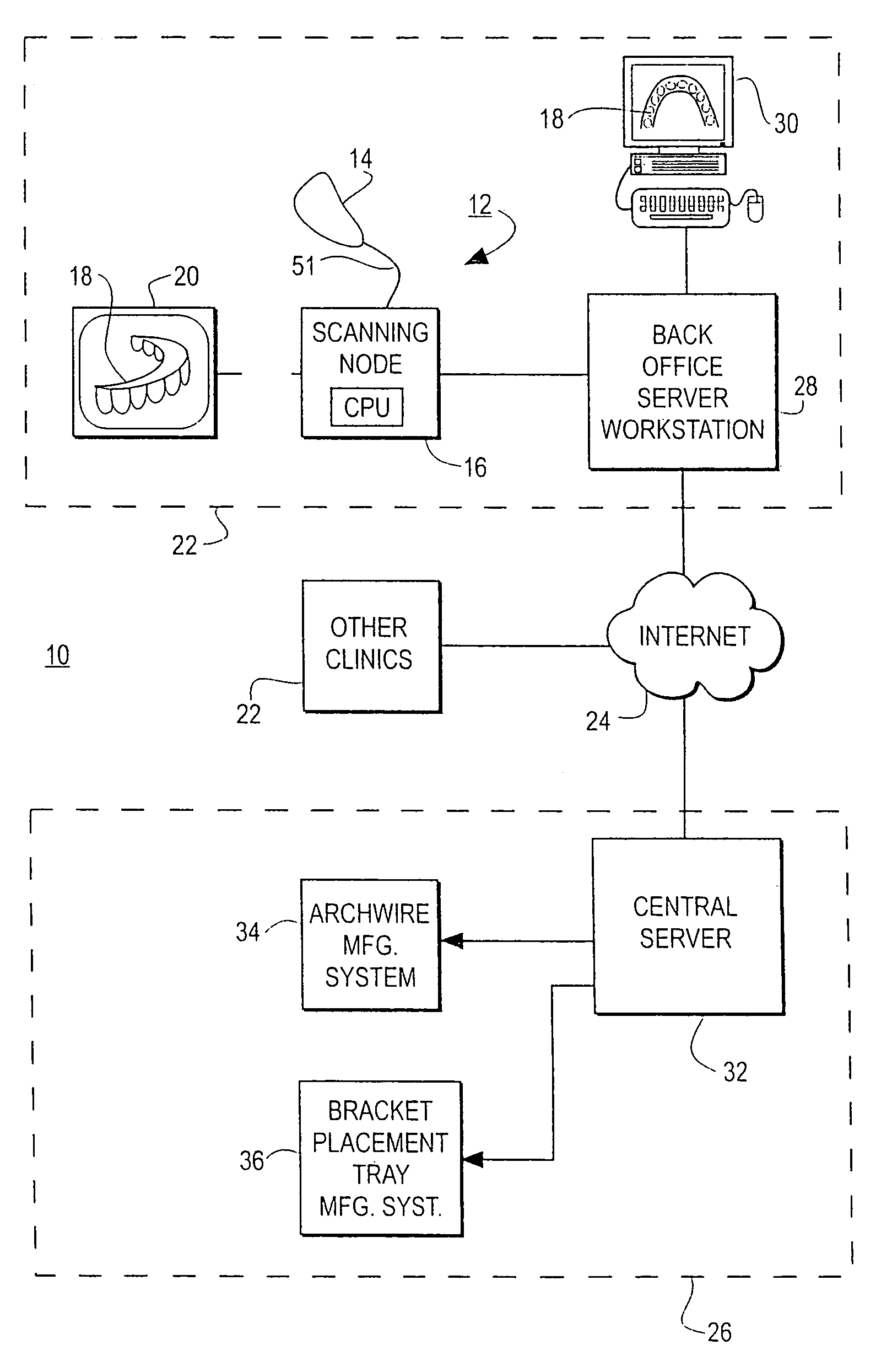
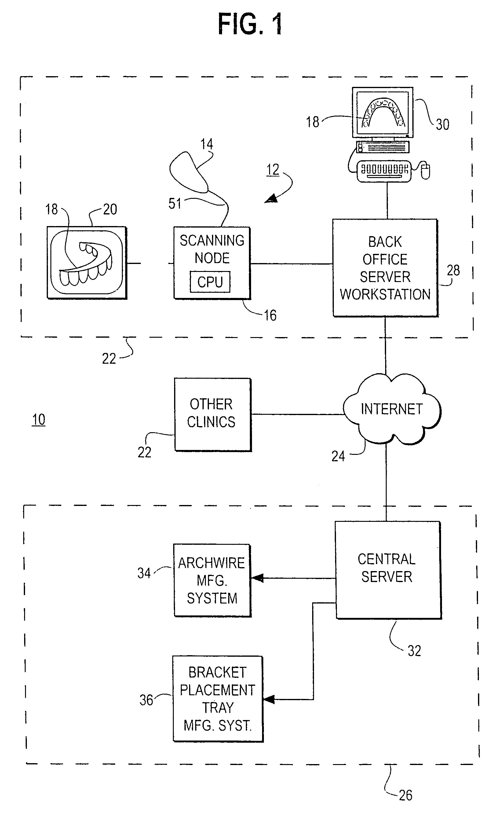
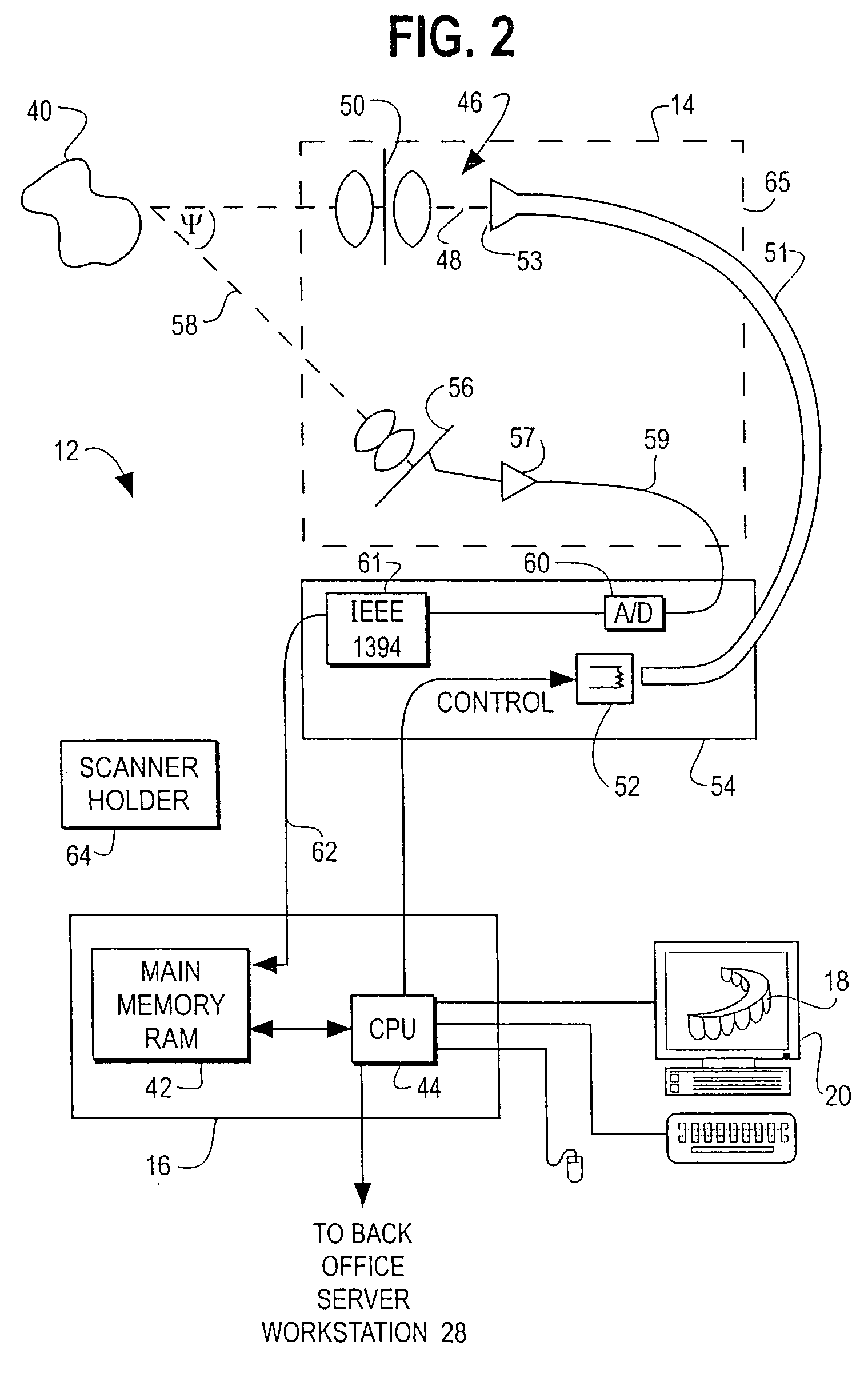
[0056]This invention relates generally to the field of orthodontics. More particularly, the invention relates to a computerized, interactive method and associated system for orthodontic treatment. The system includes a hand-held optical scanner capturing 3-dimensional information of objects, interactive computer-based treatment p...


PUM


Abstract

Interactive, computer based orthodontist treatment planning, appliance design and appliance manufacturing is described. A scanner is described which acquires images of the dentition which are converted to three-dimensional frames of data. The data from the several frames are registered to each other to provide a complete three-dimensional virtual model of the dentition. Individual tooth objects are obtained from the virtual model. A computer-interactive software program provides for treatment planning, diagnosis and appliance from the virtual tooth models. A desired occlusion for the patient is obtained from the treatment planning software. The virtual model of the desired occlusion and the virtual model of the original dentition provide a base of information for custom manufacture of an orthodontic appliance. A variety of possible appliance and appliance manufacturing systems are contemplated, including customized archwires and customized devices for placement of off-the shelf brackets on the archwires, and removable orthodontic appliances.

Description

CROSS-REFERENCE TO RELATED APPLICATIONS[0001]This is a divisional application of Ser. No. 10 / 280,758 filed Oct. 24, 2002, which in turn is a divisional application of Ser. No. 09 / 835,039 filed Apr. 13, 2001, now issued as U.S. Pat. No. 6,648,640, which is a continuation-in-part application of the following U.S. patent applications:[0002]Ser. No. 09 / 560,643 filed Apr. 28, 2000, now issued as U.S. Pat. No. 6,464,496;[0003]Ser. No. 09 / 560,131 filed Apr. 28, 2000, now issued as U.S. Pat. No. 6,744,914;[0004]Ser. No. 09 / 560,132 filed Apr. 28, 2000, now issued as U.S. Pat. No. 6,771,809;[0005]Ser. No. 09 / 560,583 filed Apr. 28, 2000, now issued as U.S. Pat. No. 6,738,508;[0006]Ser. No. 09 / 560,645 filed Apr. 28, 2000, now issued as U.S. Pat. No. 6,728,423;[0007]Ser. No. 09 / 560,644 filed Apr. 28, 2000, now issued as U.S. Pat. No. 6,413,084;[0008]Ser. No. 09 / 560,133 filed Apr. 28, 2000, now issued as U.S. Pat. No. 6,744,932;[0009]Ser. No. 09 / 560,129 filed Apr. 28, 2000, now issued as U.S. Pat...

Claims


Application Information

Patent Timeline
Patent Type & Authority Patents(United States)
IPC IPC(8): G06F19/00A61C3/00A61C7/00A61C7/14A61C9/00A61C13/00A61F2/30G06Q10/06G06T17/00
CPCA61C7/12A61C7/14G06F19/3437A61C7/28G06F19/321A61C7/146A61C7/002A61C7/00A61C9/0046G06Q10/06G06T17/00A61F2002/30953G16H50/50B33Y80/00B33Y50/00G16H80/00G16H30/40G16H40/67G16H30/20G16H20/00
Inventor RUBBERT, RUDGERWEISE, THOMASRIEMEIER, FRIEDRICHSACHDEVA, ROHITSPORBERT, PEER
Owner ORAMETRIX
Why Eureka
Try Eureka