

Injection molding method and apparatus
- Summary
- Abstract
- Description
- Claims
- Application Information
AI Technical Summary
Benefits of technology
Problems solved by technology
Method used
Image

Examples
Embodiment Construction
and the controller in one embodiment of the present disclosure;
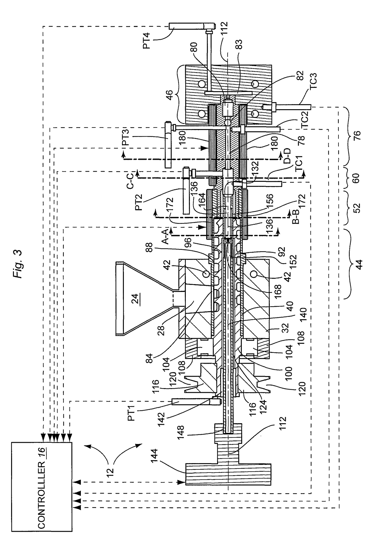
[0038]FIG. 3A is a detailed cutaway side view of portions of the plunger 160;
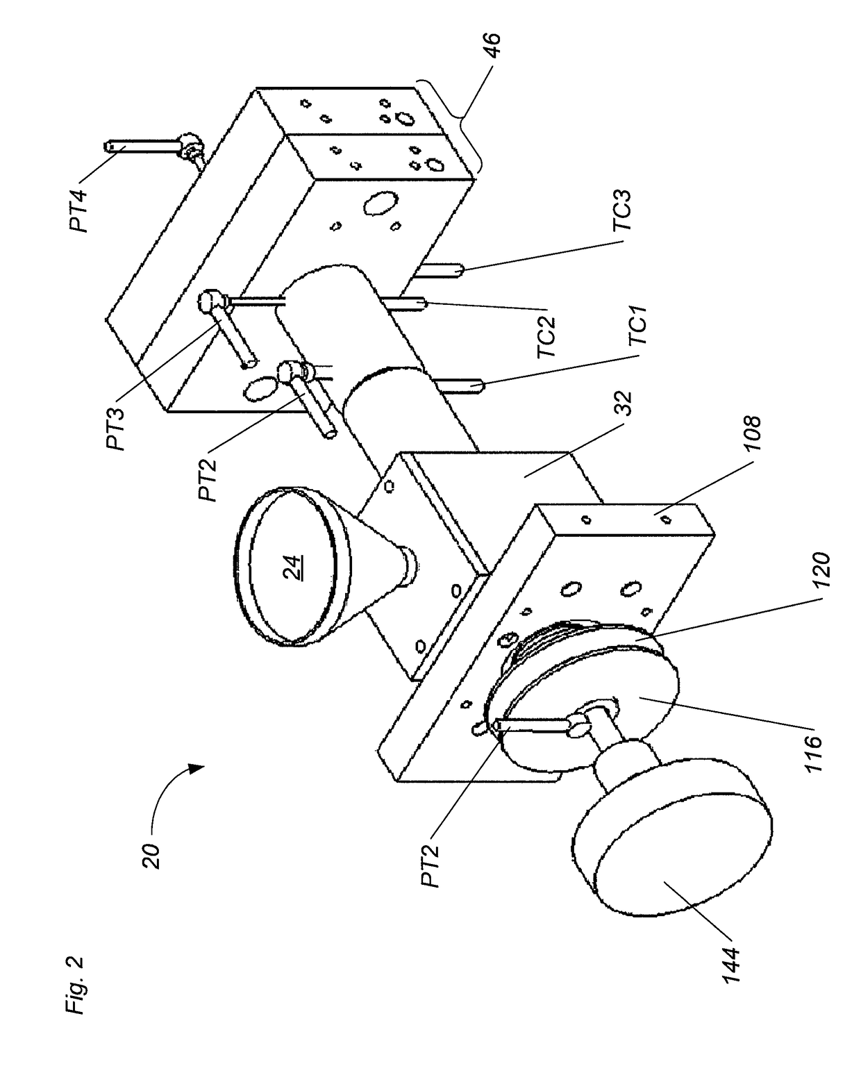
[0039]FIG. 4 is a cutaway side elevation view of the machine;
[0040]FIG. 5 is a cross-sectional view of the machine at a point indicated as A-A in FIG. 3, viewed from left to right with reference to FIG. 3;
[0041]FIG. 6 is a cross-sectional view of the machine at a point indicated as B-B in FIG. 3, viewed from left to right with reference to FIG. 3;
[0042]FIG. 7 is a cross-sectional view of the machine at a point indicated as C-C in FIG. 3, viewed from left to right with reference to FIG. 3;
[0043]FIG. 8 is a cross-sectional view of the machine at a point indicated as D-D in FIG. 3, viewed from left to right with reference to FIG. 3;
[0044]FIG. 9 is a detailed partial cutaway side elevation view of the machine; and
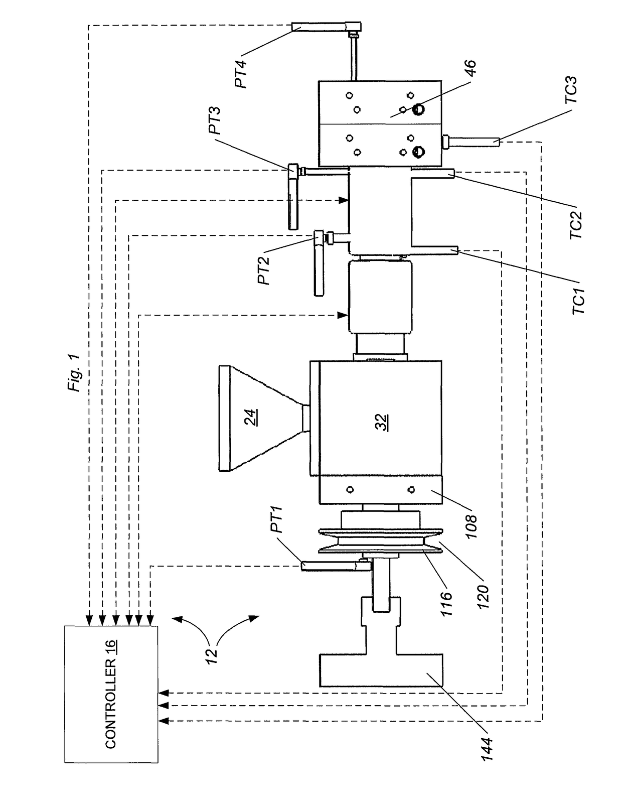
[0045]FIG. 10 is a block diagram showing components of the system 12, which includes machine 20 and controller 16 in one embodiment of the...
PUM
| Property | Measurement | Unit |
|---|---|---|
| Friction | aaaaa | aaaaa |
Abstract
Description
Claims
Application Information