Apparatus, system and methods for measuring a blood pressure gradient

a technology of fluid pressure gradient and apparatus, applied in the field of apparatus, system and methods for measuring fluid pressure gradient, can solve the problems of shortening the life of patients, significant morbidity and mortality, and restricting day to day activities, so as to achieve accurate quantification of parameters, assess or monitor physiologic performance, and minimal or negligible disruption of heart valve function.

Active Publication Date: 2014-09-04
HEMOCATH LTD
View PDF6 Cites 37 Cited by
  • Summary
  • Abstract
  • Description
  • Claims
  • Application Information

AI Technical Summary

Benefits of technology

[0048]In one embodiment, a small gauge multi-sensor wire comprises four optical pressure sensors arranged along a length, e.g. 4 cm to 7 cm, at the distal end of the wire, which allows for placement of two sensors on each side of a heart valve, to allow direct measurement of the transvalvular pressure gradient, with minimal disruption to the valve function.
[0058]Thus, a small gauge, integrated multi-sensor apparatus or “multi-sensor wire”, e.g. in the form of a micro-catheter or steerable guidewire, is provided that allows for direct measurement of a blood pressure differential or a blood pressure gradient, i.e. the comparison of real-time, direct blood pressure measurements at several locations simultaneously, within heart ventricles, arteries and / or veins during a minimally-invasive intravascular intervention. In particular, a multi-sensor wire having a diameter of 0.89 mm or less, and preferably 0.46 mm or less, provides for transvalvular pressure gradient measurements with minimal or negligible disruption of the heart valve function.
[0059]In addition, the multi-sensor wire allows for measurement of data to provide indirect measurement of a cardiac blood output and, as a consequence, estimation of the cardiac obstruction surface, i.e. the valve area.
[0060]A multi-sensor wire according to embodiments of the invention therefore provides for novel methods for directly and precisely measuring a transvalvular pressure gradient in situ for any one of the four heart valves. Beneficially, these methods provide for improvements to existing cardiovascular measurement techniques, i.e. the comparison of real-time direct blood pressure measurements at several locations simultaneously, e.g. upstream, across and downstream of the heart valve, for each of the four heart valves, during minimally-invasive (percutaneous intravascular) cardiovascular procedures.
[0061]Such methods provide measurements that enable cardiologists to more accurately quantify parameters or data indicative of the severity of valve disease, such as structural valve stenosis, and then promptly identify the diagnosis and provide the appropriate treatments to patients. In addition, following a heart valve procedure, such as valvuloplasty or valve replacement, clinicians can assess or monitor the physiologic performance of the new or repaired heart valve.
[0064]Thus, apparatus, systems and methods are provided that mitigate problems with known methods and apparatus for measuring pressure gradients, and in particular provide for direct measurement of intravascular or transvalvular pressure gradients and flow.

Problems solved by technology

Heart valve disease or dysfunction can, in severe cases, substantially restrict day to day activities and shorten the lives of patients.
These operations are associated with significant morbidity and mortality according to multiple risk factors related to age.
However, both valve repair and replacement techniques remain particularly expensive and are associated with important risks for the patients.
Even though echo-cardiography remains the most frequently used method for confirmation of diagnosis, it is limited by the echogenicity of the patient, valvular calcifications and sub-valvular calcifications, as well as the presence of concomitant mitral valve pathology.
However, in this technique there is an exaggeration of the transvalvular pressure gradient since one of the catheters rests through the valve.
This last technique is clearly less reliable since, firstly, the measurements of the aortic and ventricular pressures are not simultaneous and secondly, the withdrawal of the catheter frequently involves a benign transitory cardiac arrhythmia, which distorts the pressure curves.
Firstly, it is not ideal to use different types of devices for comparing the two pressures.
It is therefore too limp and fragile for reliably positioning it for pressure measurements within the heart, where higher blood flows and significant turbulence in the flow tends to cause movement of the sensor at the end of the wire.
This diagnostic shows the location and severity of lesions but accuracy is compromised by the sequential nature of the data.
A problem with guidewires equipped with sensors based on electrical signals is that multiple, long electrical connections to each sensor must be provided.
Use of microelectronics and long electrical wires, particularly when used in humid biological conditions, tends to cause reliability issues with measurement of small electrical signals, e.g. from parasitic capacitances, noise and electromagnetic interference (EMI), and limits the ability to integrate multiple electrical sensors within a guidewire to measure pressure gradient and flow.
Furthermore, there may be significant risks involved with the use of microelectronics and electrical connections in vivo, particularly in the region of the heart, where electrical activity may disrupt normal heart function.
The electronic drift of MEMS sensors integrated into guidewires remains a limitation.
This presents a number of challenges in providing a guidewire with more than one electrical sensor.
In addition, MEMS sensors along with their long electrical connections significantly increase the complexity of manufacturing assembly processes of guidewires using electrical sensors, and therefore significantly increasing their manufacturing costs.
Typically, guidewires for medical use are fabricated to be disposable (i.e. for single use only) and are significantly expensive.
However, another challenge for medical applications, as described above, is that to measure pressure gradients, pressure sensors are required having sufficient sensitivity to detect small pressure differences reliably within the region of interest.
Some available optical sensors are either too large to allow for multiple sensors to be accommodated in a small gauge device, and / or they do not have sufficient sensitivity.
These designs are quite complex and would appear to be a challenge to fabricate consistently.
More significantly, the sensor elements will be sensitive to stresses when the fiber is bent or twisted, such that it would be difficult to discriminate fiber stresses from actual pressure readings.
Thus, even if they could be manufactured with sufficiently small diameters, these and similar configurations would not be suitable for intravascular or intravalvular use which necessitate bending of the fiber in the region of the sensors.
However, apparatus is not currently known or available to cardiologists for directly measuring in situ blood pressure gradients simply and quickly, particularly transvalvular pressure gradients, where a catheter with a diameter of 0.89 mm (0.035″) and preferably 0.46 mm (0.018″) or less is needed to minimize disruption to normal heart valve activity and over estimation of transvalvular gradient.

Method used


Image

  • Apparatus, system and methods for measuring a blood pressure gradient
  • Apparatus, system and methods for measuring a blood pressure gradient
  • Apparatus, system and methods for measuring a blood pressure gradient

Examples


second embodiment

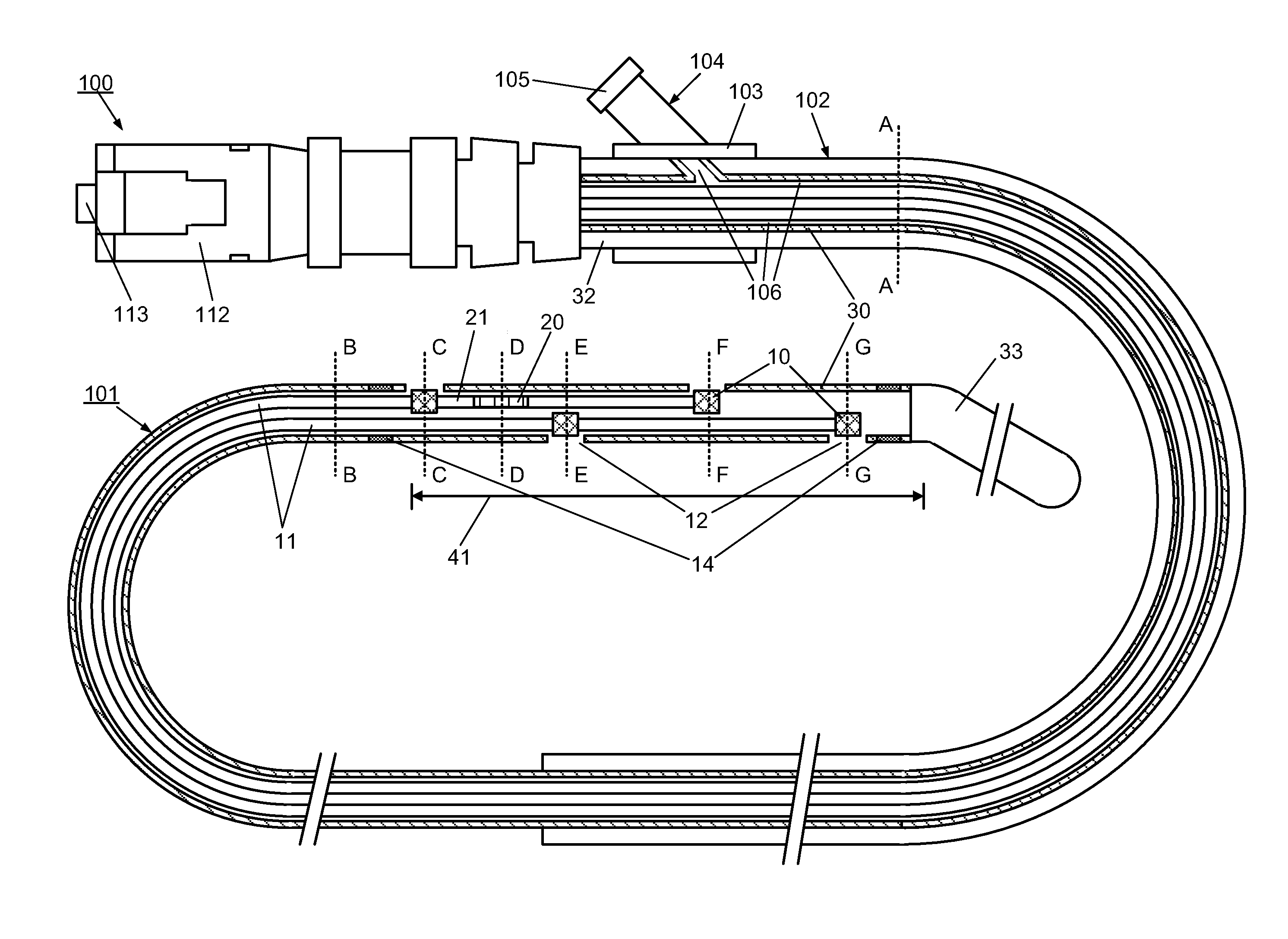
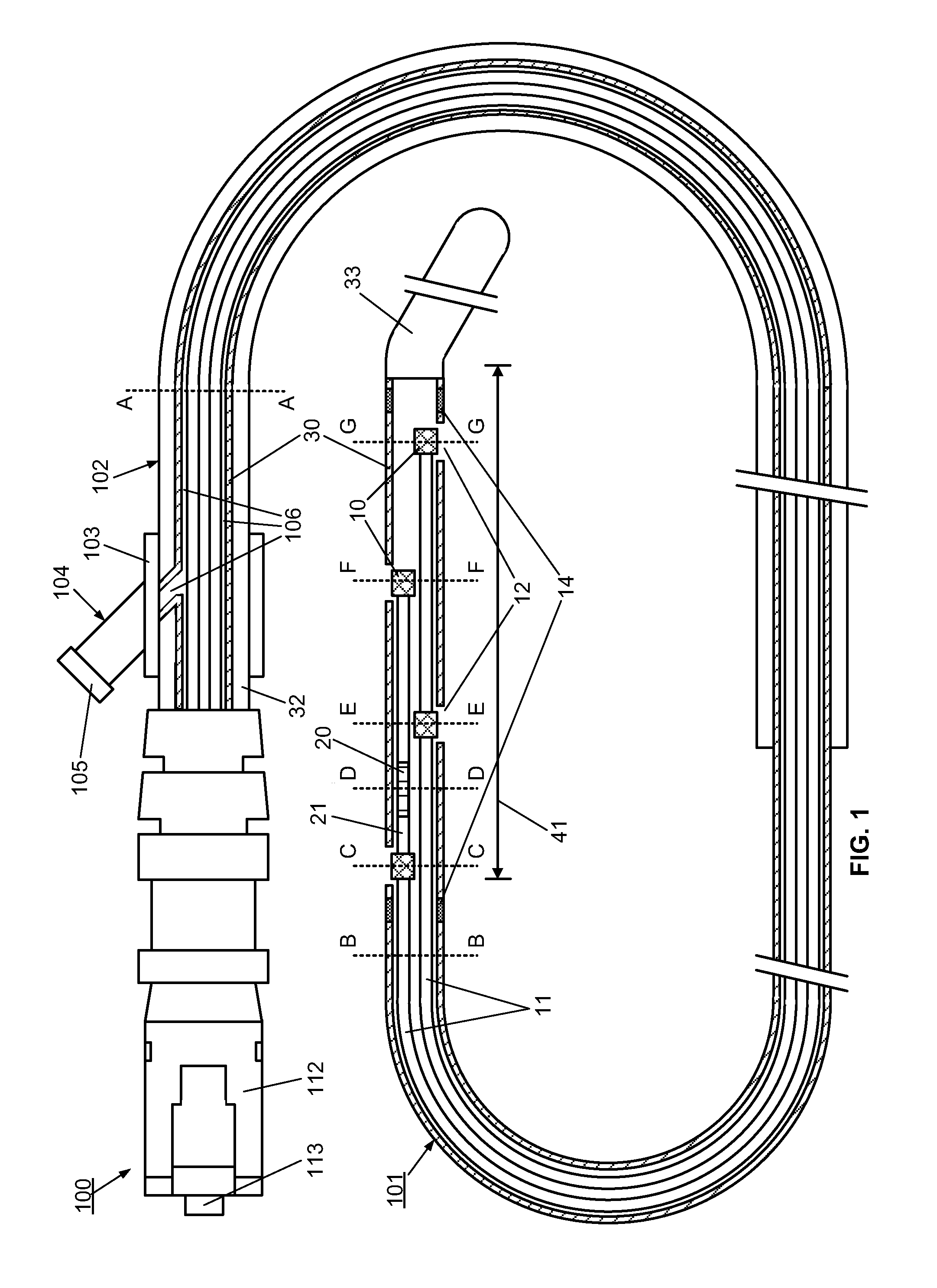
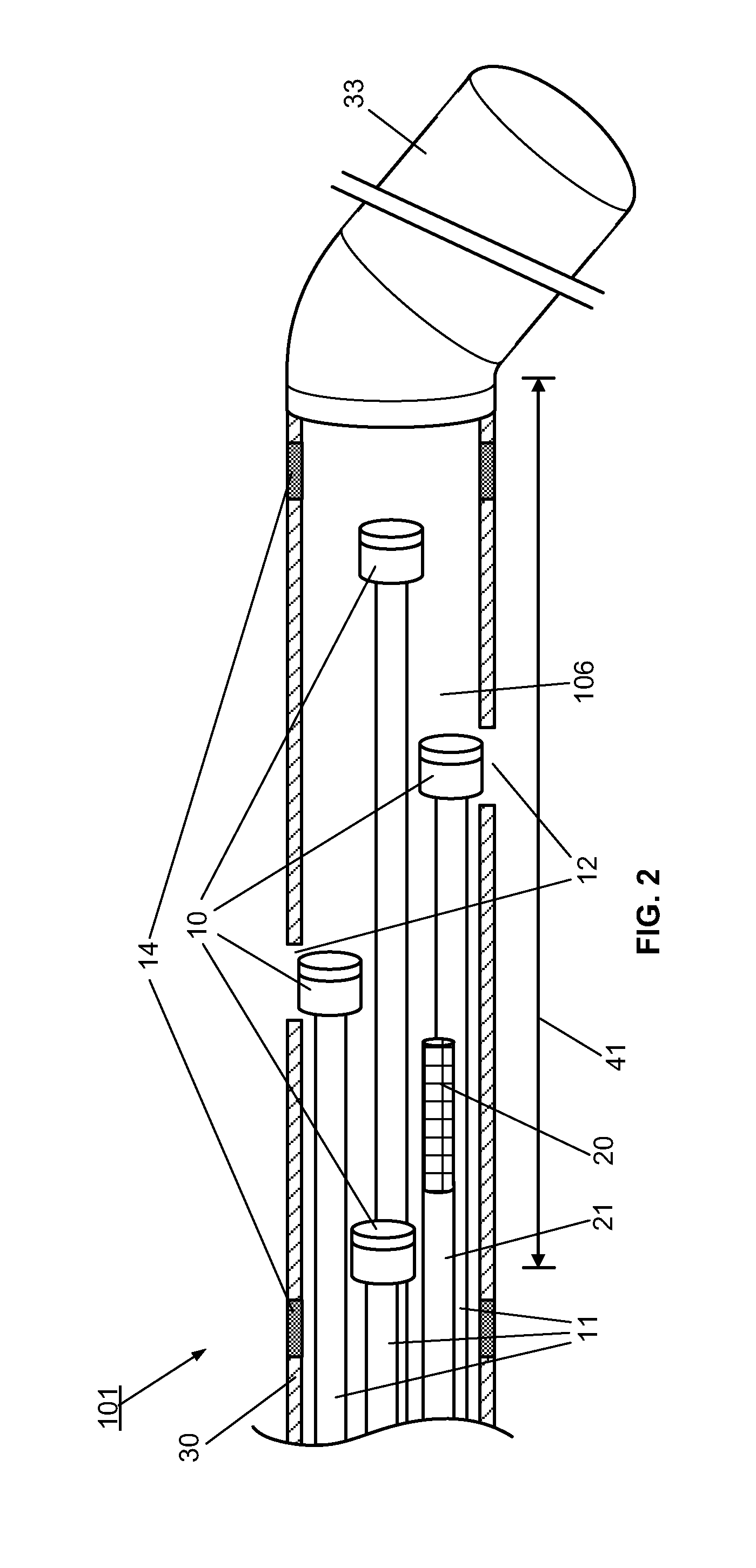
[0095]However, the use of the optical multi-sensor wire 100 in the form of a micro-catheter will first be described very briefly, so as to introduce a second embodiment in which the multi-sensor wire takes the form of a guidewire.

[0096]In summary, in use of the optical multi-sensor wire 100 in the form of a micro-catheter, for measurement of intravascular or transvalvular blood pressure gradients and flow, a cardiologist would first introduce a guide / support catheter to allow the optical multi-sensor wire to be quickly introduced into the region of interest. A guide catheter may already be in place for other cardiac procedures. If not, conventionally, this would involve first introducing a conventional guidewire, which can be torqued using established techniques, for other intravascular or cardiac procedures. Such a guidewire typically includes a J tip and has suitable flexibility and torque characteristics to allow it to be steered and guided to position the type in the region of i...

first embodiment

[0111]A method, according to the present invention, for measuring and monitoring the blood pressure gradient across the aortic valve 211, i.e. the aortic transvalvular pressure gradient, in a human heart 200 using a multi-sensor wire 100 according an embodiment, such as described with reference to FIGS. 1 to 4, is described below with reference to FIG. 8. A conventional guidewire is first inserted into a peripheral artery, such as the femoral or carotid, using known techniques, and advanced through the ascending aorta 210. A support catheter 160 is then slid over the guidewire. The operator then advances and positions the support catheter 160 in proximity to the aortic valve 211, using visualization devices such as radio-opaque markers on its distal end. The operator then replaces the guidewire by the multi-sensor wire 100 in the lumen of the support catheter 160. The operator advances and positions the distal end of the multi-sensor wire 100 into the left ventricle 212 using visual...

third embodiment

[0113]A method, to measure and monitor the blood pressure gradient across the tricuspid valve 222, i.e. the tricuspid transvalvular pressure gradient, in a human heart 200, is described below and illustrated by FIG. 10. A guidewire is first inserted into a peripheral large vein, such as the inferior vena cava 220, using known techniques, and advanced through the ascending vein 220 to the right atrium 221. The support catheter 160 is then slid over the guidewire. The operator then advances and positions the support catheter 160 in proximity to the tricuspid valve 222, using visualization devices such as radio-opaque markers on its distal end. The operator then replaces the guidewire by a multi-sensor wire 100 in the lumen of the support catheter 160. The operator advances and positions the distal end of the multi-sensor wire 100 into the right ventricle 223 using visualization devices such as radio-opaque markers 14 on its distal end. Once the multi-sensor wire 100 is properly posit...


PUM


Abstract

An apparatus (100), control system (150) and methods are provided for directly measuring a pressure gradient, i.e. by real-time pressure measurements, with particular application for in situ measurement of transvalvular blood pressure gradients for the aortic valve and other heart valves, using minimally-invasive techniques. The apparatus takes the form of a multi-sensor assembly, e.g. enclosed within a micro-catheter or a steerable guidewire, and comprises a plurality of optical pressure sensors (10) is arranged along a length of the distal end portion (101), for measuring pressure simultaneously at each sensor location. For example, four MOMS optical pressure sensors (10), and optionally, a flow sensor (20), are incorporated into a distal end portion (101) having a diameter of 0.89 mm or less, and preferably 0.46 mm or less. Beneficially, all sensors are optically coupled, via respective optical fibers (11), to an optical coupler (112) at the proximal end of the multi-sensor apparatus, without requiring electrical connections.

Description

CROSS-REFERENCE TO RELATED APPLICATIONS[0001]This application claims priority from U.S. provisional patent application No. 61 / 552,778 entitled “Apparatus, system and methods for measuring a blood pressure gradient”, filed Oct. 28, 2011 and from U.S. provisional patent application No. 61 / 552,787 entitled “Fluid temperature and flow sensor apparatus and system for cardiovascular and other medical applications”, filed Oct. 28, 2011, both of which are incorporated herein by reference, in their entirety.TECHNICAL FIELD[0002]This invention relates to an apparatus, system and methods for measuring fluid pressure gradients, and in particular, relates to measurement of blood pressure gradients and flow within the heart or blood vessels, including measurement of transvalvular blood pressure gradients.BACKGROUND ART[0003]In vertebrate animals, the heart is a hollow, muscular organ having four pumping chambers: the left and right atria and the left and right ventricles, each being provided with...

Claims


Application Information

Patent Timeline
Patent Type & Authority Applications(United States)
IPC IPC(8): A61B5/00A61B5/026A61B8/08A61B5/0205G16H20/40
CPCA61B5/6855A61B8/488A61B5/0261A61B5/02055A61B5/026A61B5/6852A61B5/0215G01F1/6884G01P5/10G01K11/32G01K13/02G16H40/63A61B5/01G16H20/40A61B5/0295A61B5/0002A61B5/024A61B5/02154A61B5/6851
Inventor CARON, ERICBILODEAU, LUCPAQUETTE, MICHEL
Owner HEMOCATH LTD
Why Eureka
Try Eureka