Solenoid valve

a solenoid valve and valve body technology, applied in the direction of valve details, valve operating means/release devices, valves, etc., can solve the problems of relatively high manufacturing cost, inability to make any valve opening desired, and inability to manufacture parts. to achieve the effect of reducing the number of components

Inactive Publication Date: 2003-12-11
FESTO AG & CO KG
View PDF1 Cites 17 Cited by
  • Summary
  • Abstract
  • Description
  • Claims
  • Application Information

AI Technical Summary

Benefits of technology

0005] One object of the invention is to provide a solenoid valve of the...

Problems solved by technology

This known solenoid valve comprises a relatively large number of parts, something which entails relatively expensive manufacture.
Since...

Method used


Image

  • Solenoid valve
  • Solenoid valve
  • Solenoid valve

Examples


Embodiment Construction

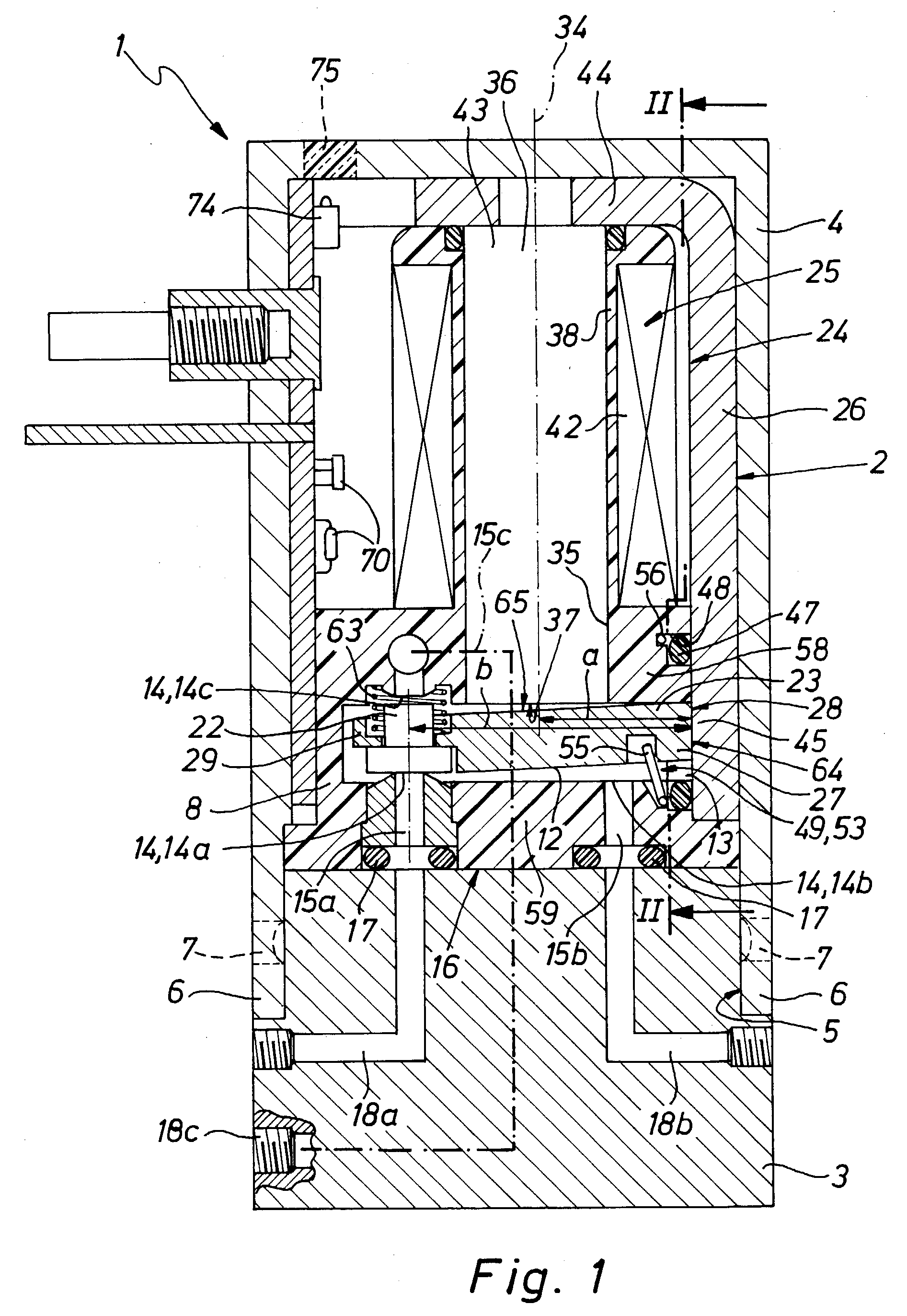
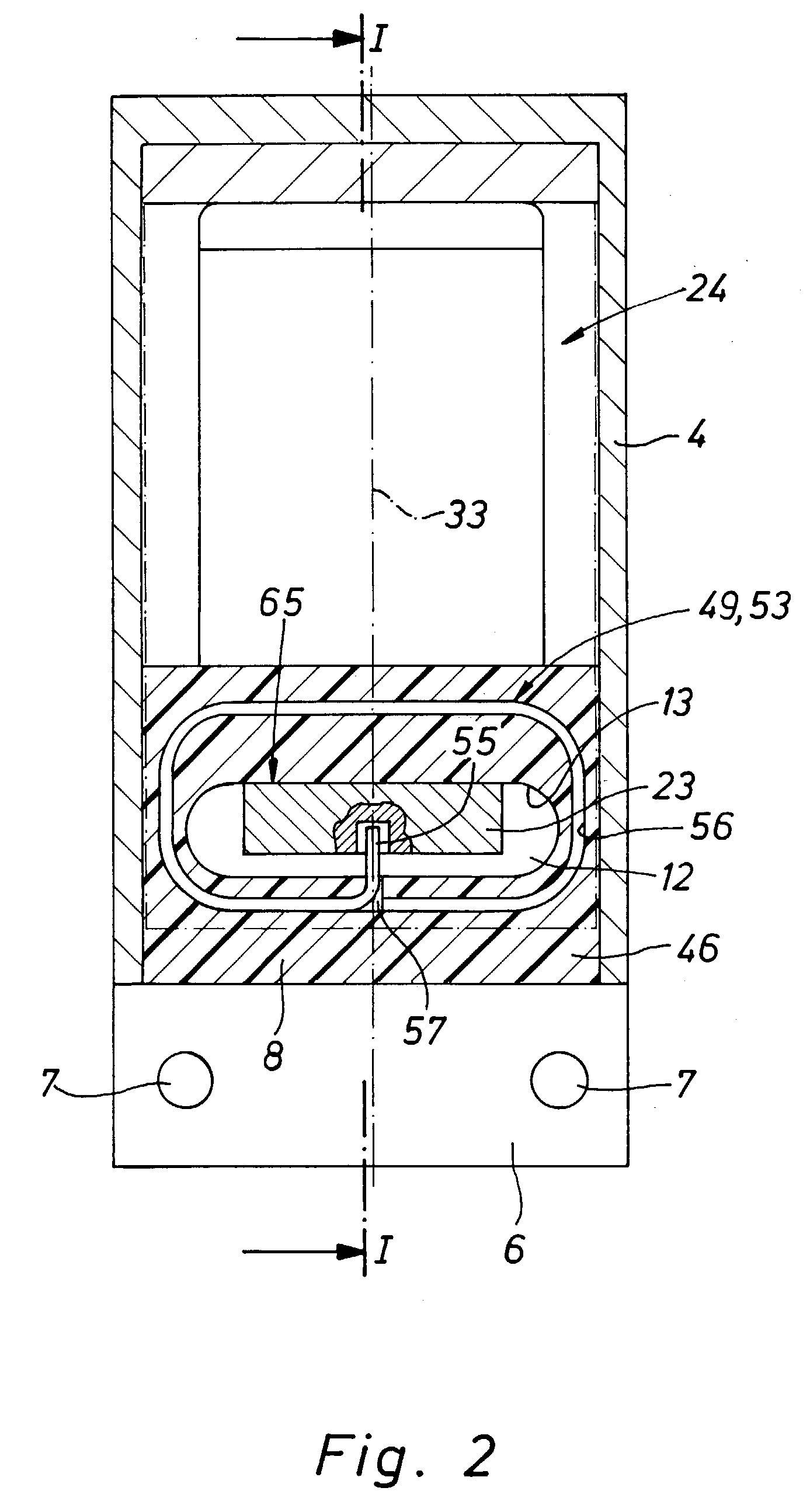
[0023] The solenoid valve generally referenced 1 comprises a valve unit 2, depicted in separately again in FIG. 3, which is mounted on a connection body 3 and is surrounded by a hood 4. The hood 4 is slipped over the valve unit 2 and is attached by attachment lugs 6, provided adjacent to the hood opening 5, by pins or some other suitable means on the connection body 3. The corresponding attachment means are indicated at 7.

[0024] The valve unit 2 comprises a preferably plastic valve housing 8. In the valve housing 8 a shallow, elongated valve chamber 12 is formed, preferably by a pocket-like recess in the valve housing 8. At one end of the valve chamber 2 there is an opening sealed in a pressure-tight manner, which in the following will be termed the installation opening 13.

[0025] In the case of the solenoid valve 1 of the working example it is a question of a 3 / 2 way valve. That is to say three valve openings 14 are directed into the valve chamber 12, which constitute a supply openi...


PUM


Abstract

A solenoid valve has an electromagnet with a clapper armature. The clapper armature is installed in a valve chamber, which is provided with an installation opening for the installation of the clapper armature. The electromagnet is provided with a yoke means, which directly closes the installation opening with a closure section. The clapper armature bears in a pivotal fashion at the rear against this closure section.

Description

[0001] The invention relates to a solenoid valve comprising an electromagnet having a coil with an associated yoke means and furthermore a clapper armature for the operation of at least one closing valve member, and a valve housing bearing the coil, said housing having a valve chamber containing the clapper armature with the closing valve member, into which valve chamber an installation opening for the clapper armature is directed, said installation opening being aligned as an extension of the clapper armature and being closed in a sealing manner.THE PRIOR ART[0002] In the case of a solenoid valve disclosed in the European patent publication 1 172 592 A2 of this type the clapper armature is seated on two yoke pins extending through the valve chamber of a frame-like yoke means. During assembly the clapper armature is inserted through an initially open installation opening into the valve chamber, following which the installation opening is sealed off by a plug-like closure part.[0003]...

Claims


Application Information

Patent Timeline
IPC IPC(8): F16K31/06
CPCF16K31/0682Y10T137/86622Y10T137/86847
Inventor FRISCH, HERBERT
Owner FESTO AG & CO KG
Why Eureka
Try Eureka