Object shape transformation device

a technology of object shape and transformation device, which is applied in the field of object shape transformation device, can solve the problems of difficulty for users to understand the meaning of function and intuitively operate parameters, and the prior art cannot deal with the transformation of objects

Inactive Publication Date: 2003-12-25
PANASONIC CORP
View PDF9 Cites 8 Cited by
  • Summary
  • Abstract
  • Description
  • Claims
  • Application Information

AI Technical Summary

Problems solved by technology

In the above-mentioned prior art, however, the mixed function is given by a complex equation of motion using a direct current servo motor system, spring constant, attenuation coefficient and the like and therefore it is difficult for the user to understand the meaning of the function and operate the parameters intuitively.
The above-mentioned prior art cannot deal with the transformation of the object like this.

Method used


Image

  • Object shape transformation device
  • Object shape transformation device
  • Object shape transformation device

Examples


first embodiment

[0046] (The first embodiment)

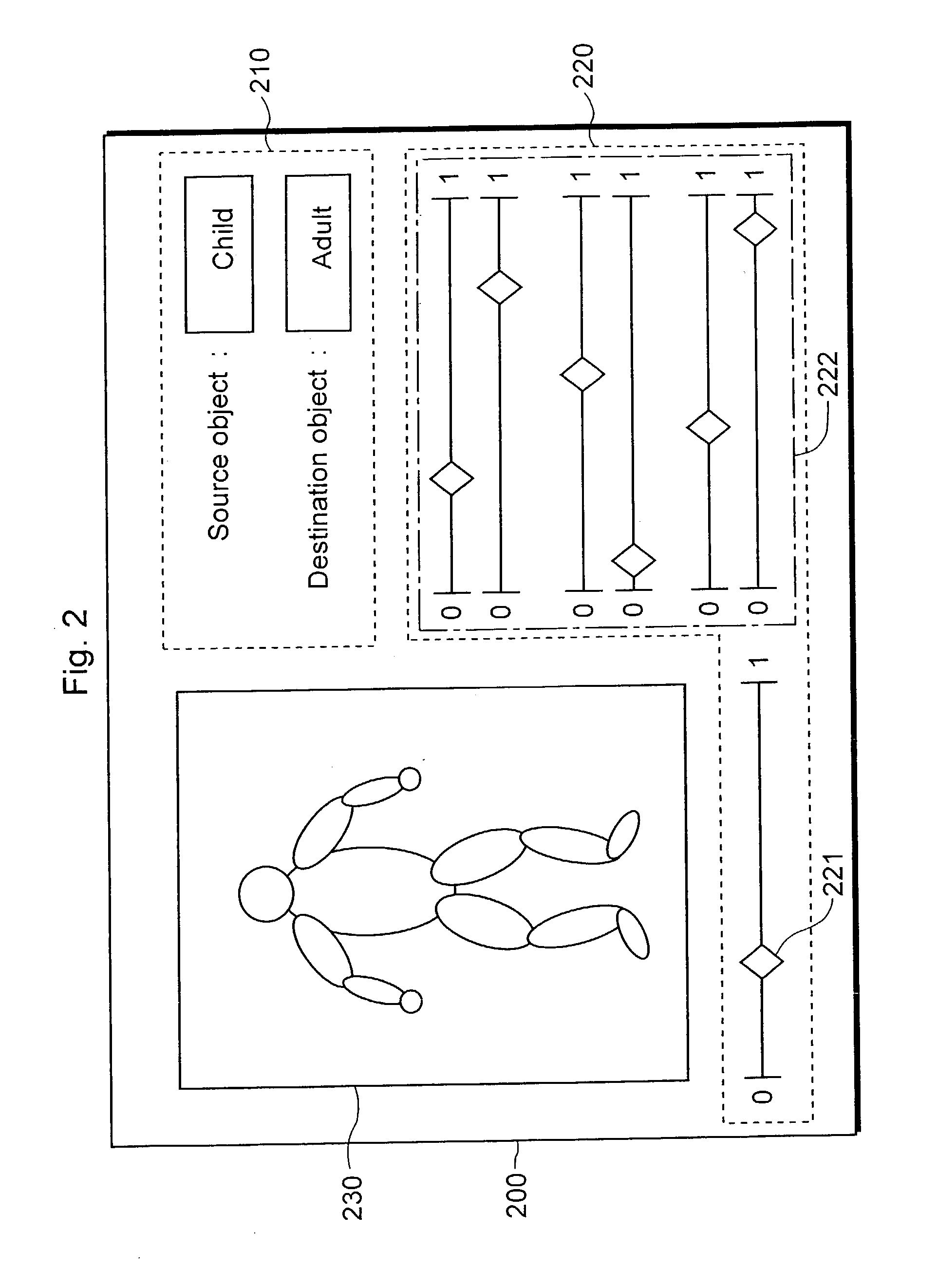
[0047] An object shape transformation device according to the first embodiment of the present invention will be explained below with reference to figures. In addition, in the first embodiment, a three-dimensional character like a human being is cited as an example and explained as an object (i.e. an object put in the CG space), but the present invention is applicable to an arbitrary object. Additionally, the object used in the first embodiment shall be structured by a one-skin polygon model.

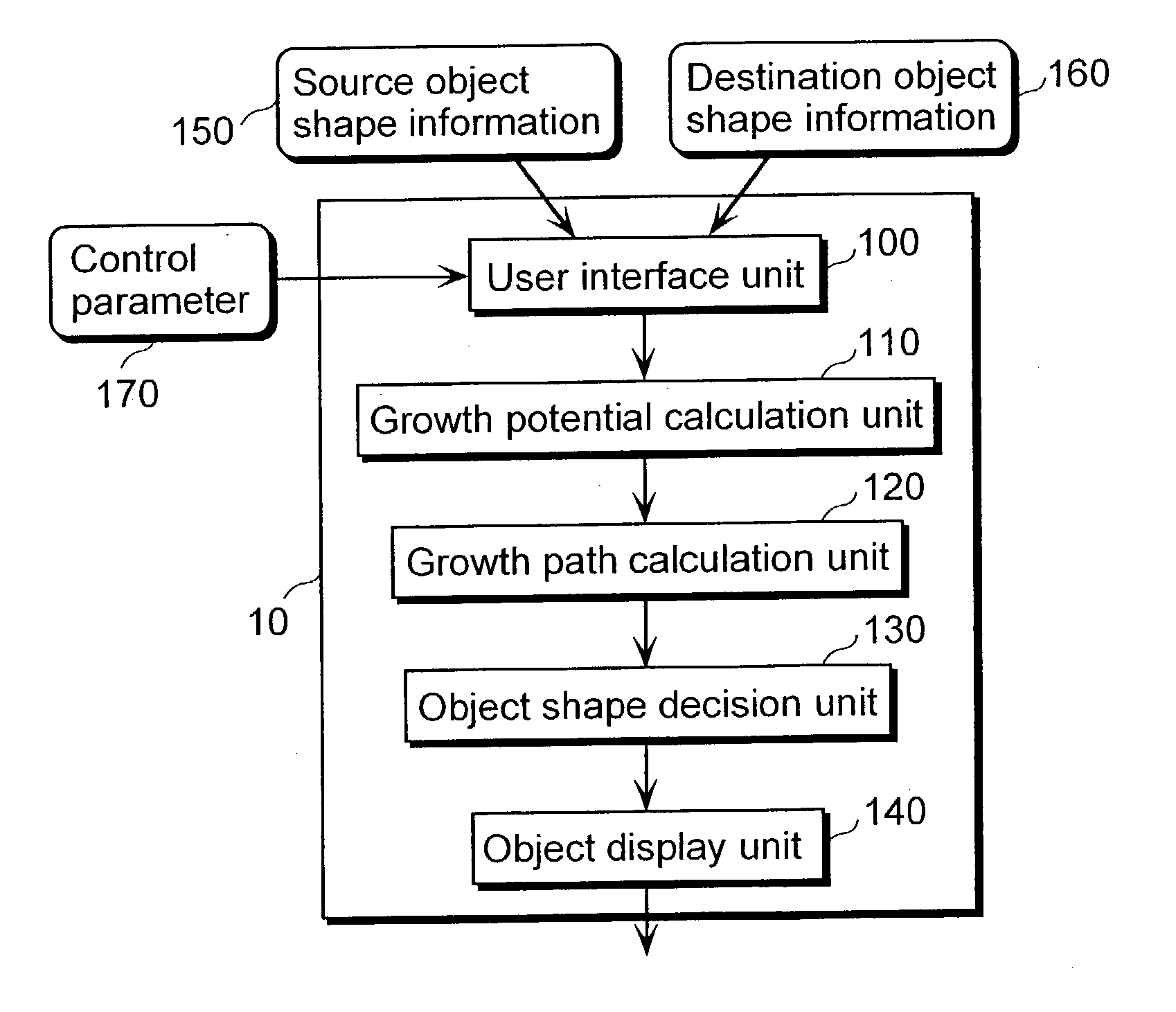
[0048] FIG. 1 is a diagram that shows an example of a structure of an object shape transforming device according to the first embodiment.

[0049] An object shape transformation device 10 according to the first embodiment comprises: a user interface unit 100; a growth potential calculation unit 110; a growth path calculation unit 120; an object shape decision unit 130; and an object display unit 140.

[0050] In the user interface unit 100, a user sets up source object shap...

second embodiment

[0103] (The second embodiment)

[0104] An object shape transformation device according to the second embodiment of the present invention will be explained below with reference to figures. In addition, in the second embodiment, as an object, a character like a human being who has a hierarchical structure is cited as an example and explained but the present invention is applicable to an arbitrary object that has a hierarchical structure. An object used in the second embodiment shall be made up of the head, the arms, the legs and the body; each of them is an independent segment and is connected according to the hierarchical structure. Additionally, the hierarchical structure of the source object matches that of the destination object. Here, "segments" are display elements that make up the above-mentioned object and are operable as one. Further, similarly to the first embodiment, as for the source object and the destination object used here, correspondence among the vertexes of each segme...

third embodiment

[0120] (The Third Embodiment)

[0121] An object shape transformation device according to the third embodiment of the present invention will be explained below with reference to figures. In addition, a source object used in the third embodiment is a character object that has the hierarchical structure similar to that used in the second embodiment (refer to FIG. 9). As for the object used for the transformation of each part (hereafter called "a parts object"), the correspondence between the segments and vertexes of the source object that corresponds to the parts object shall be determined in advance.

[0122] FIG. 15 is a diagram that shows an example of a structure of the object shape transformation device according to the third embodiment. An object shape transformation device 600 comprises a user interface unit 610 into which parts object shape information 630 can be inputted in addition to the source object shape information 150 and the control parameter 170. Note that in FIG. 15, the ...


PUM


Abstract

An object shape transformation device 10, for a start, accepts from a user a setting of shape information of an object at the time before and after the transformation and a parameter that controls growth potential affecting shape transformation of an object in a user interface unit 100. Then the device 10 calculates the growth potential required for shape transformation in a growth potential calculation unit 110 and decides a transformation path using the calculated growth potential in a growth path calculation unit 120. Next, the device 10 decides the shape of the object using the calculated transformation path and a temporal parameter in an object shape decision unit 130 and an object display unit 140 displays the object.

Description

[0001] (1) Field of the Invention[0002] The present invention relates to an object shape transformation device that transforms a shape of an object used in computer graphics and particularly to the object shape transformation device that controls a path in the case of transforming an object into another object.[0003] (2) Description of the Prior Art[0004] Computer graphics (hereafter called "CG") are widely used and special effects realized by using CG are indispensable for creating video. Morphing, a technique that transforms smoothly from an object to another object, is its representative example. As the prior art on the shape transformation like this, there is "an action display generation method in computer graphics" disclosed by the Japanese Laid-Open Patent Application No. H8-55233.[0005] In this conventional "action display generation method in computer graphics", for a start, displacement vectors at the first time and the second time of points that make up of an object are s...

Claims


Application Information

Patent Timeline
Patent Type & Authority Applications(United States)
IPC IPC(8): G06T13/40
CPCG06T2210/44G06T13/40
Inventor UESAKI, AKIRAMOCHIZUKI, YOSHIYUKIHIJIRI, TOSHIKIORIMOTO, KATSUNORIOHTSUKI, TOSHIKAZUASAHARA, SHIGEO
Owner PANASONIC CORP
Why Eureka
Try Eureka