Wick, plate type heat pipe and container

a heat pipe and wicking technology, applied in the field of wicks, plate types of heat pipes, containers, etc., can solve the problems of water not being used as working fluid in the container made of aluminum, applying the above-mentioned method to seal the container, and difficult to form the container shown in fig. 11 which is made of copper by extrusion

Inactive Publication Date: 2004-01-22
NODA HAJIME +3
View PDF8 Cites 21 Cited by
  • Summary
  • Abstract
  • Description
  • Claims
  • Application Information

AI Technical Summary

Problems solved by technology

However, when the heat pipe comprises a plate type heat pipe, it is impossible to apply the above-mentioned method to seal the container. FIG. 14 shows a conventional portion to be sealed in the plate type heat pipe.
However, although the aluminum container shown in FIG. 11 can be formed by extrusion, it is difficult to form the container shown in FIG. 11 which is made of copper by means of extrusion.
However, there is a problem in which water cannot be used as working fluid in the container made of aluminum.
More specifically, aluminum reacts with water to deteriorate the function of the heat pipe.
However, in the plate type heat pipe shown in FIG. 12, there is a problem in which it is difficult to insert the mesh stably in the container, thus producing the heat pipes with different property.
Furthermore, a conventional wick comprising mesh, braid or wire has the following problem.
However, even if the wire is received within the container, it is very difficult to securely fix the wire on the inner surface of the container in view of the structure of the container so as to form the acute angle portion therebetween.
When the wire is not securely fixed on the inner surface of the container, for example, the side surface of the wire is partly contacted with the inner surface of the container, the wire does not effectively function as the wick.
In addition, there is the following problem in the plate type heat pipe using the above-mentioned conventional wick.
However, the conventional wick does not effectively function.
Furthermore, the conventional portion to be sealed has the following problem.
Furthermore, in case of the conventional container formed by extrusion shown in FIG. 11, the heat transfer along the X direction (i.e., the direction across the partition member of the container) is inferior to the heat transfer along the Y direction (i.e., the direction along the partition member).
More specifically, when copper material is selected as the material for the container and the wick which can use water as a working fluid, it is impossible to practically place a copper wire having a diameter up to 0.5 mm.phi. along the inner surface of the container.
However, in that case, since the vaporized fluid is not supplied to the wires wound on one of the sides of the thin copper plate, i.e., the vaporized fluid is supplied to the wires wound on the other side of the thin copper plate, there occurs no condensation of the working fluid in the above-mentioned side of the thin copper plate, thus causing to provide dead space.
In addition, in case that the wire is wound along one direction on the surface of thin plate, the function of circulating working fluid is effective in one direction, thus the function of the plate type heat pipe is limited.
However, although the above-mentioned type of the wick secures the passage for vaporized fluid in upper side of the container formed by the protruding portions, the vaporized working fluid only condenses there, since there is no circulating structure.
Aluminum is excellent in workability, however, water cannot be used with aluminum container.

Method used


Image

  • Wick, plate type heat pipe and container
  • Wick, plate type heat pipe and container
  • Wick, plate type heat pipe and container

Examples


example 1

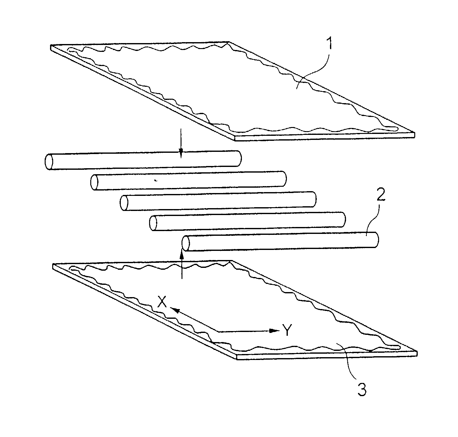
[0134] According to the present invention, a container of a plate type heat pipe of the present invention is formed by using two copper plate having a thickness of 0.2 mm, a width of 20 mm and length 50 mm, ten pieces of copper wire of a diameter of 0.2 mm.phi. and length of 50 mm, and 4 sheets of #200 screen meshes, as follows:

[0135] 10 pieces of the copper wires are placed in parallel each other with 2 mm pitch on one of the copper plate, and then 4 sheets of the meshes are interposed between the disposed wires and the other copper plate. Solder is applied in advance to the side portions of the copper wire to contact with the copper plate and the mesh, and each end of the meshes. A square bar is placed on each end of the copper plate so as to seal the container.

[0136] Then, thus formed copper plates with the copper wire and meshes placed and pinched by a fixing fig are introduced into a furnace as they are.

[0137] In addition, a small copper tube is interposed in advance so as to e...

example 2

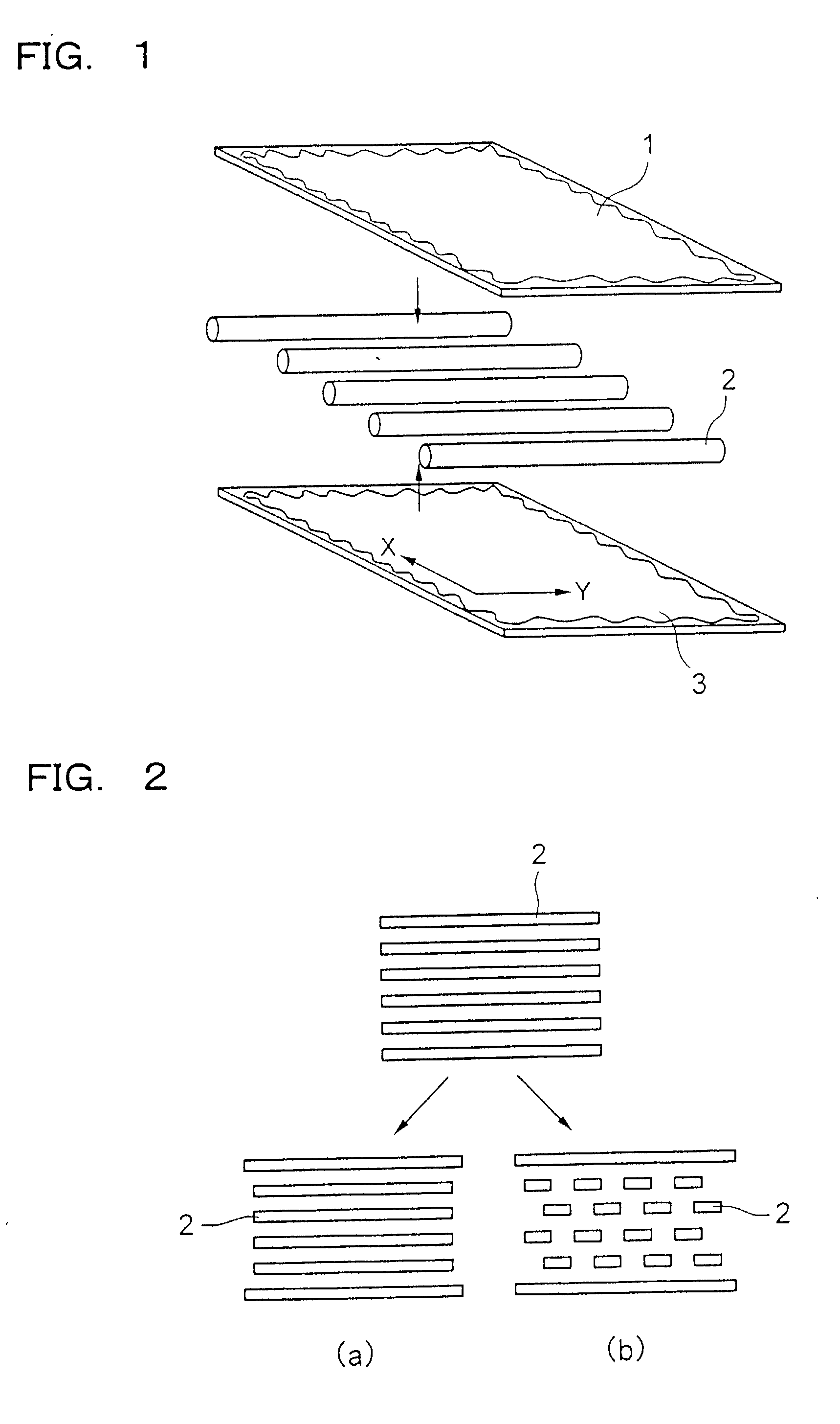
[0138] The same material as in Example 1 except the following material are used and a plate type heat pipe of the present invention is formed in the same manner as in Example 1 except the following. More specifically, 4 sheets of the meshes are divided into respective 2 sheets. The group of copper wires placed in parallel are interposed between a set of 2 sheets of meshes, and then, thus formed copper wires and meshes are interposed by two copper plates to form a plate type thin heat pipe of the present invention having a width of 20 mm, a length of 50 mm, and a thickness of 1 mm. When a chip generating heat was cooled by thus formed plate type thin heat pipe of the present invention, the chip was effectively cooled.

example 3

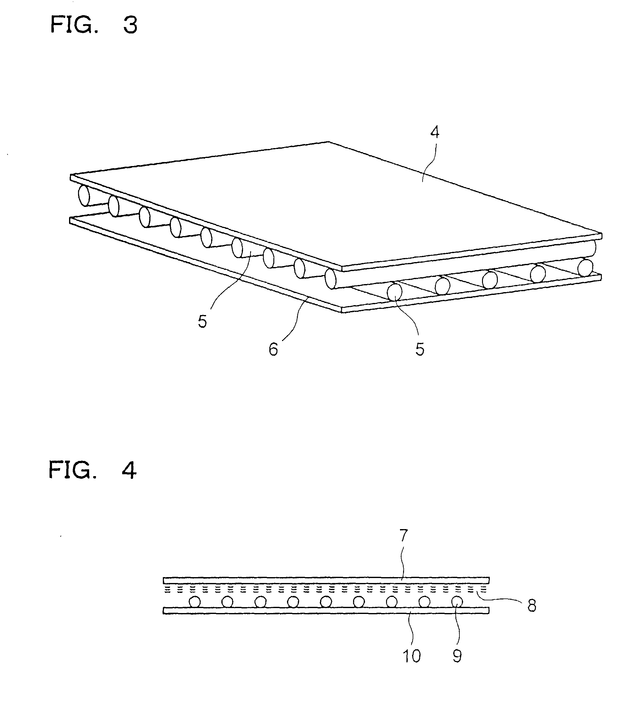
[0139] According to the present invention, the plate type heat pipe of the present invention schematically shown in FIG. 3 is formed by using two copper plate having a thickness of 0.2 mm, a width of 40 mm and a length 60 mm, 36 pieces of copper wire of a diameter of 0.3 mm.phi. and length of 60 mm, and 56 pieces of copper wire of a diameter of 0.3 mm.phi. and length of 40 mm, as follows:

[0140] Copper wires 5 are placed in parallel each other with 1 mm pitch on one of the copper plate 4. Solder is applied in advance to the side portions of the copper wire to contact with the copper plate. Copper wires are bundled before being cut to be the above mentioned size, and applied tensile force, and then pressed and adhered to the end portions of the copper placed below, thus forming a unit. In the same manner, another unit in which copper wires 5 are placed on the copper plate 5 is formed.

[0141] The above-mentioned two units are placed face to face in such manner the axis directions of the...


PUM


Abstract

A plate type thin heat pipe comprises: a group of wire members comprising a plurality of first metal wire members placed in a same plane in parallel with a prescribed distance spaced out, and a plurality of second metal wire members placed in a same plane in parallel with a prescribed distance spaced out and placed so as to cross the plurality of first metal wire members; a container having a hollow portion which is reduced in inner pressure and hermetically sealed comprising an upper plate member and a lower plate member placed face to face, each of which is made of thin copper plate, formed in such a manner that each of the upper plate member and the lower plate member contacts the group of wire members, and the group of wire members are sandwiched by the upper and lower plate members, and water as a working fluid received in the container.

Description

[0001] This application is a divisional of U.S. patent application Ser. No. 09 / 655,664, filed Sep. 6, 2000, the entire disclosure of which is hereby incorporated by reference, and which claims priority to Japanese Application Nos. 1999-252748, filed on Sep. 7, 1999, and 1999-252749, filed on Sep. 7, 1999. This application is related to U.S. Non-Provisional application Ser. No. 10 / ______ , filed on even date herewith (having attorney docket number KAWAW6.001DV2), the entire disclosure of which is hereby incorporated by reference.[0002] 1. Field of the Invention[0003] The present invention relates to a plate type heat pipe, wick and container used for cooling electronic devices.[0004] 2. Description of the Related Art[0005] As one of the means to effectively dissipate the heat generated from semiconductor chips in the electronic devices which has been increasing, there is proposed a heat pipe. In particular, a plate type heat pipe is perceived to be effective among various heat pipes ...

Claims


Application Information

Patent Timeline
Patent Type & Authority Applications(United States)
IPC IPC(8): F28D15/02F28D15/04F28F3/00G06F1/20
CPCF28D15/046F28D15/0233
Inventor NODA, HAJIMEKAWABATA, KENYANAKAMURA, TOSHIAKINIEKAWA, JUN
Owner NODA HAJIME
Why Eureka
Try Eureka