Liquid cooling arrangement for electric machines

a technology for electric machines and liquid cooling, which is applied in the direction of cooling/ventilation arrangement, dynamo-electric components, and magnetic circuit shapes/forms/construction, etc. it can solve the problems of poor efficiency of such a cooling arrangement, risk of motor failure, and inability to provide an electric machine with apertures. , to achieve the effect of improving the liquid cooling arrangemen

Inactive Publication Date: 2004-01-22
DANA TM4 INC
View PDF31 Cites 91 Cited by
  • Summary
  • Abstract
  • Description
  • Claims
  • Application Information

AI Technical Summary

Benefits of technology

0005] An object of the present invention is therefore to provide an improved liquid cooling arrangement for electric machines.

Problems solved by technology

The efficiency of such a cooling arrangement is poor since air is a generally non-efficient cooling fluid.
Furthermore, some electric machine operate in environment that are such that it is not possible to provide an electric machine with apertures.
A drawback of Nakamura's system is the risk of failure of the motor caused by leaks.
Indeed, a failure-causing link could spring should the seal between adjacent laminations fail.

Method used


Image

  • Liquid cooling arrangement for electric machines
  • Liquid cooling arrangement for electric machines
  • Liquid cooling arrangement for electric machines

Examples


first embodiment

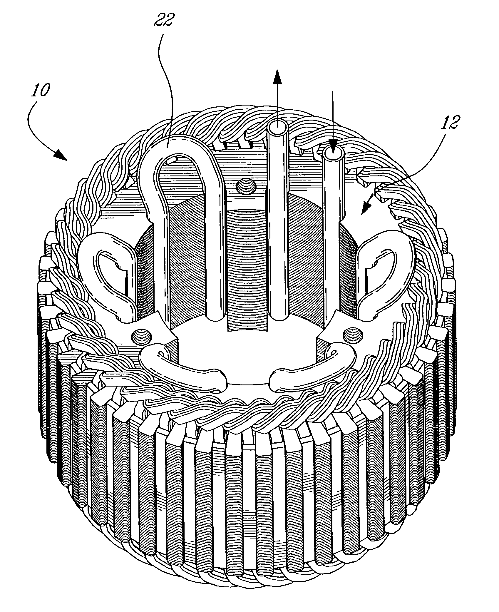
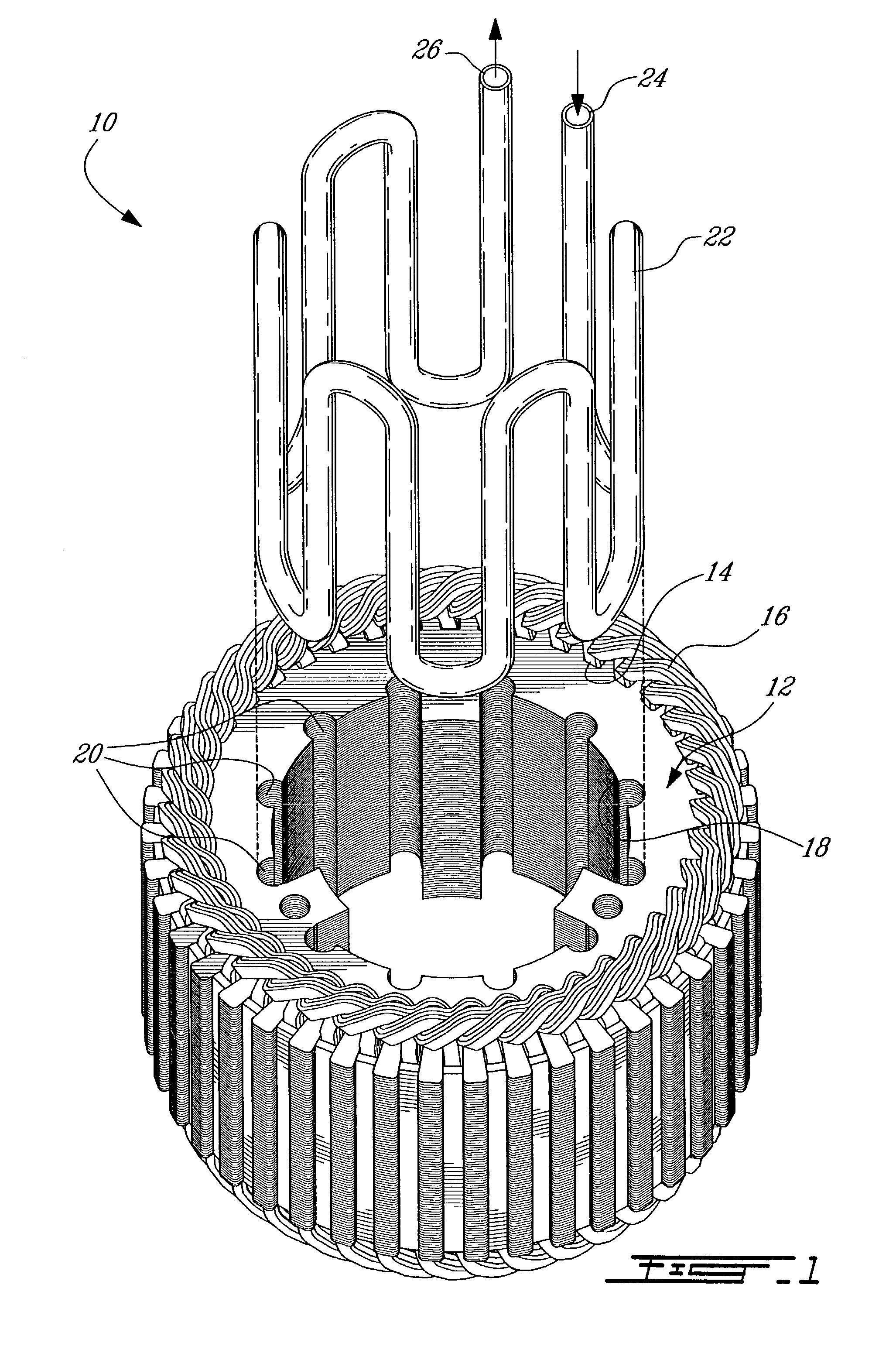
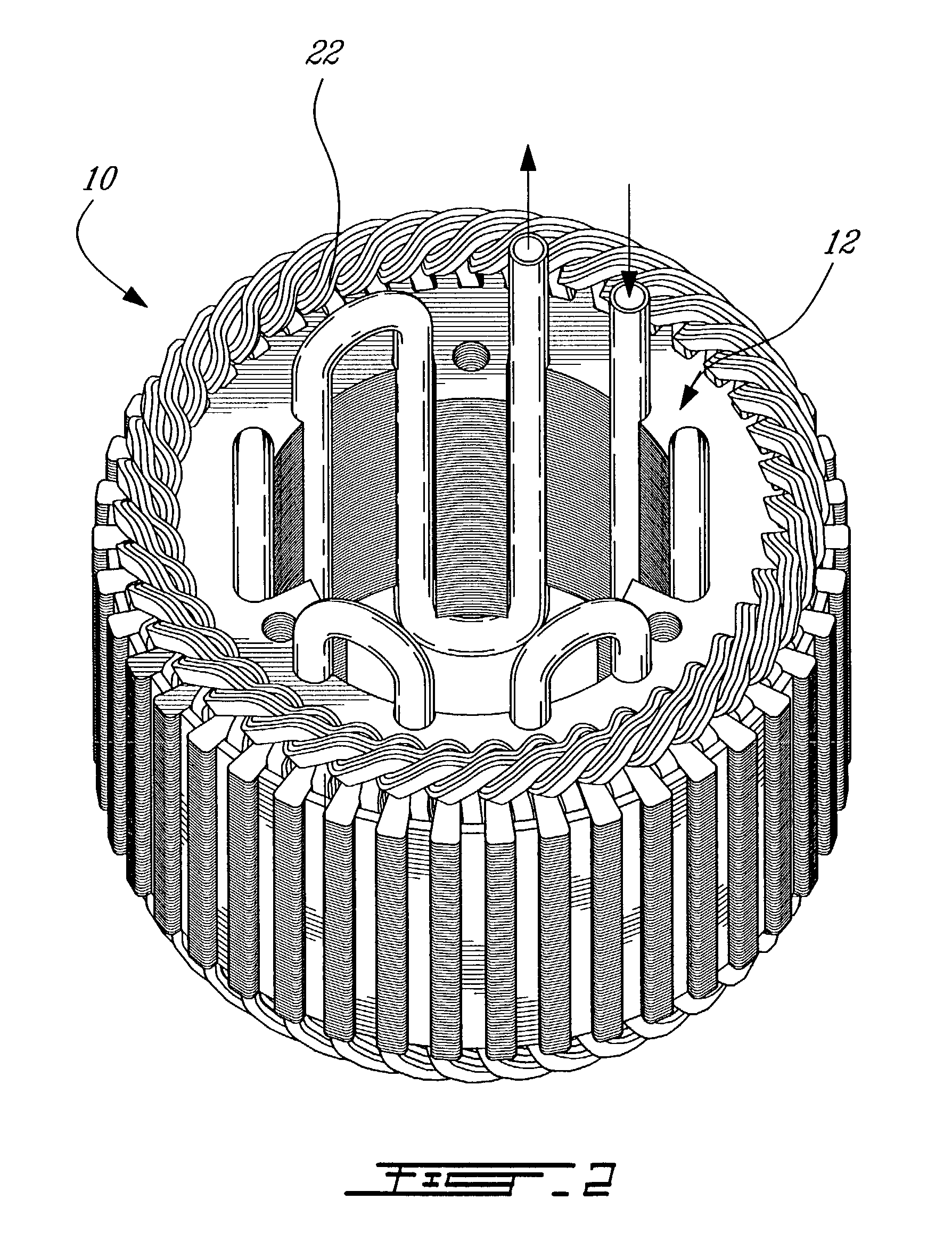
[0030] In a nutshell, the present invention, illustrated in FIGS. 1 to 5b, uses the laminations of the stator as a heat storing element provided with generally C-shaped channels in which a cooling tube is mounted. In operation, cooling fluid is circulated in the cooling tube to extract heat stored in the laminations.

second embodiment

[0031] the present invention, illustrated in FIGS. 6 to 9, uses a separate heat storing element also provided with generally C-shaped channels in which a cooling tube is mounted. The heat storing element is then inserted in the stator of an electric machine with the cooling tube in contact with both the heat storing element and the stator. In operation, cooling fluid is circulated in the cooling tube to extract heat accumulated in the heat storing element and in the stator.

[0032] Turning now to FIGS. 1 to 5b a cooling arrangement 10 according to the first embodiment of the present invention will now be described.

[0033] FIG. 1 shows a stator 12 of an electric machine (not shown). The stator 12 is made of a plurality of identical laminations stacked together. The stator 12 is generally cylindrical and includes rectangular external channels 14 in which coils 16 are mounted. It is to be noted that the stator 12 is a so-called internal stator, i.e. that the rotor (not shown) is so mounte...


PUM


Abstract

A cooling arrangement for electric machines comprising a heat storing element provided with generally C-shaped channels and a cooling tube so configured and sized as to be insertable in said C-shaped channels of said heat storing element is described herein. The cooling tube, once inserted in the channels is deformed to conform to the C-shaped channels, whereby heat stored in said heat storing element is extracted by circulating cooling fluid inside the cooling tube.

Description

[0001] The present invention relates to electric machines. More specifically, the present invention is concerned with a liquid cooling arrangement for electric machines.[0002] Electric machines, wether they be motors or generators, are well known in the art. It is also widely known that electric machines generate heat as a by-product and that this heat must be somehow extracted from the machine to improve the performances of the machine and prevent early degradation of the machine.[0003] Conventionally, electric machines are often air-cooled. This is easily done by providing apertures in the body of the machine to let air be forced therein. The efficiency of such a cooling arrangement is poor since air is a generally non-efficient cooling fluid. Furthermore, some electric machine operate in environment that are such that it is not possible to provide an electric machine with apertures.[0004] Electric machines using cooling fluid have also been designed. For example, European Patent ...

Claims


Application Information

Patent Timeline
Patent Type & Authority Applications(United States)
IPC IPC(8): H02K1/20H02K5/20H02K15/00
CPCH02K1/20H02K15/00H02K5/20H02K5/203Y02E60/14
Inventor HOULE, MARTINLANGLOIS, ANDRE
Owner DANA TM4 INC
Why Eureka
Try Eureka