
Optical communication system and method

a communication system and optical technology, applied in the field of optical communication systems and methods, can solve the problems of requiring longer connection distances, affecting performance at shorter distances, and affecting the performance of optical elements,

Inactive Publication Date: 2004-02-12
CORNING INC
View PDF16 Cites 37 Cited by
  • Summary
  • Abstract
  • Description
  • Claims
  • Application Information

AI Technical Summary

Problems solved by technology

For example, Internet traffic tends to travel much longer distances than conventional voice circuits and therefore require longer connection distances, i.e. longer connection circuits.
However, acceptable performance at maximum reach does not necessarily result in acceptable performance at shorter distances.
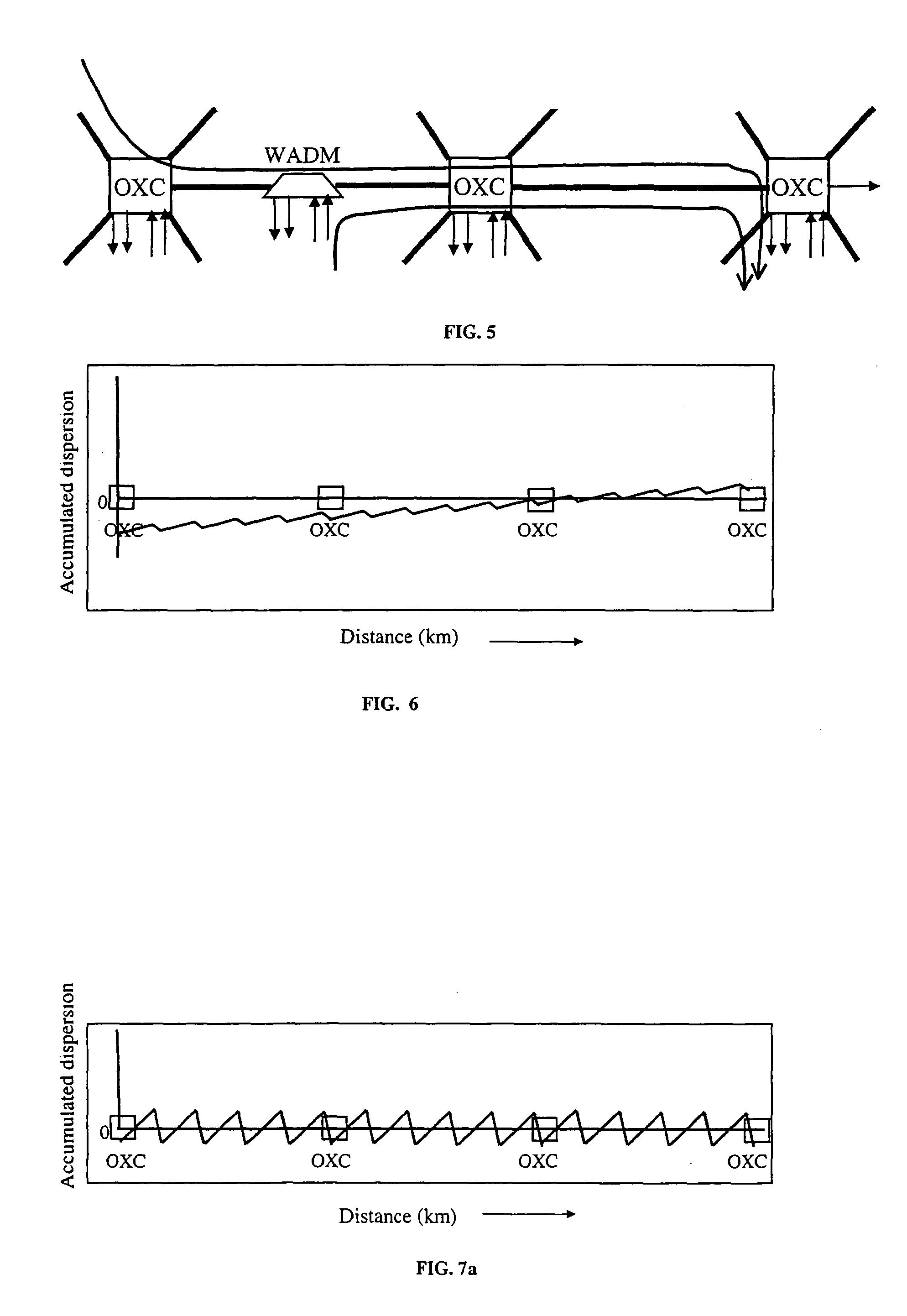
Therefore, dispersion management requirements in optical networks are quite different than in point-to-point systems since WDM channels arriving at the same node may have originated from different locations or points and therefore may have different amounts of accumulated dispersion, thereby possibly impacting the capability for traffic add / drop at any point across the network.
Generally, the use of large dispersion pre-compensation (e.g. large negative dispersion) can result in a large dispersion induced eye-closure penalty for the transmitted signals, and consequently the signal performance will degrade.
However, eventually the magnitude of the dispersion will take on such large values that the performance will quickly drop below acceptable levels.
In this example for the case of -1000 ps / nm pre-compensation, the optical path distance at which such large values of dispersion occur is estimated to be about 5000 km. FIG. 12 shows that although a larger pre-compensation value might optimize the performance at longer reaches, acceptable performance may not be achieved at shorter reaches due to large dispersion-induced penalties.
However, post-compensation without pre-compensation in otherwise similar networks generally would tend to limit the reach of the system by several hundred kilometers (as compared to pre-compensation only) because post-compensation will reduce the linear dispersion penalty but will not help in reducing non-linear penalties as much as the pre-compensation-only solution.

Method used


Image

  • Optical communication system and method
  • Optical communication system and method
  • Optical communication system and method

Examples


Embodiment Construction

[0102] In the experimental network setup schematically depicted in FIG. 14, eighty (80) channels were added at one node occupied by a broadcast-and-select optical add / drop multiplexer (B&S OADM). The 80 channels propagated over 1600 km of optical fiber (passing through 4 OADMs) and at the fifth OADM 50% of the signal traffic, i.e. an even number of channels, was dropped and 50% new traffic was added, whereafter the new set of 80 channels were circulated to the remaining spans.

[0103] The optical add / drop multiplexers (OADMs) or optical cross-connect nodes (OXCs) utilized in the setup were based on "broadcast-and-select" architecture (B&S), enabled by a wavelength-selective switch. The B&S OADM architecture is schematically illustrated in FIG. 15 for an OADM and in FIG. 16 for an OXC. The architecture comprises a 1.times.1 wavelength-selective switch or blocker, such as the DSE.TM. wavelength-selective switch from Corning Incorporated, Corning, N.Y., in combination with 1.times.2 powe...


PUM


Abstract

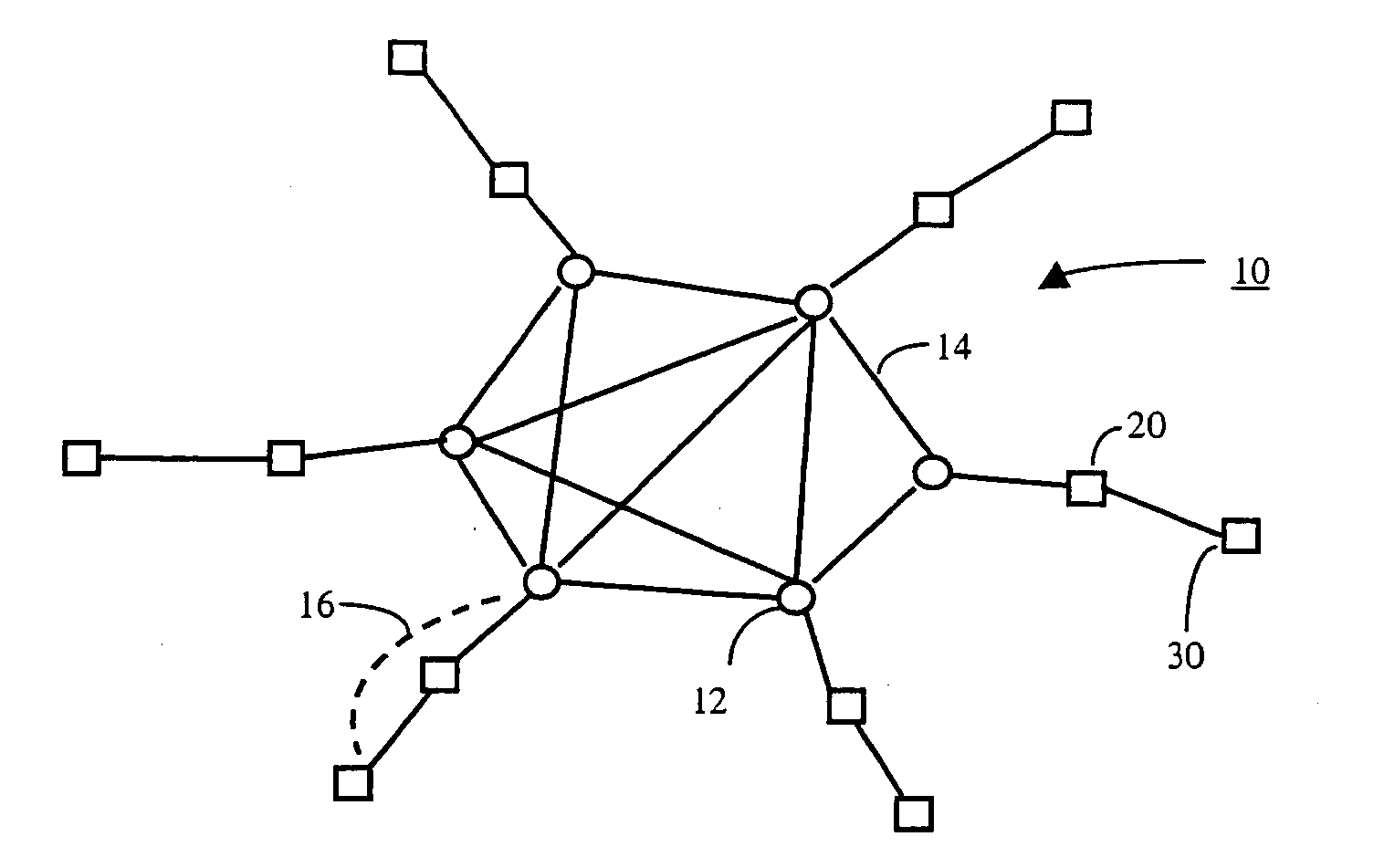
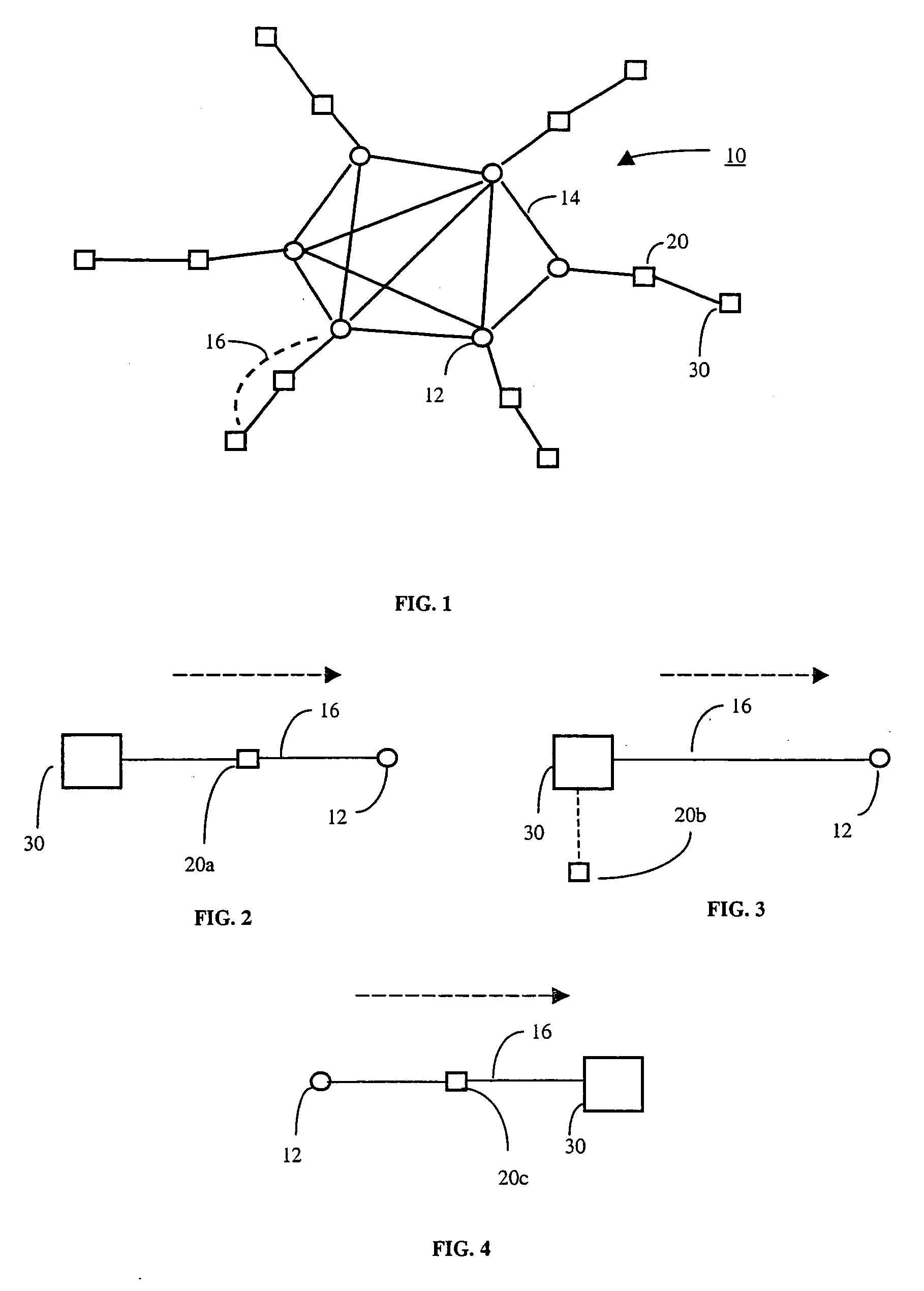
An optical communication system that includes an optical network is disclosed having a plurality of nodes and a plurality of optical fiber links which includes optical fiber links that interconnect the nodes. Signals passing through the network are similarly pre-compensated and / or similarly post-compensated. The network preferably includes dispersion-managed optical fiber spans, and preferably further includes distributed amplification, preferably erbium amplifiers and / or Raman amplifiers. Preferably, the network is transparent.

Description

[0001] 1. Field of the Invention[0002] The present invention relates to optical communication systems and methods of communicating over optical fiber networks.[0003] 2. Technical Background[0004] Rapidly growing IP traffic, including data and Internet traffic, along with the requirement for networking high-capacity traffic-pipes originating from various locales, have resulted in a growing interest in long-haul and ultra-long-haul (ULH) networks, and in particular for terrestrial networks. For example, Internet traffic tends to travel much longer distances than conventional voice circuits and therefore require longer connection distances, i.e. longer connection circuits.[0005] For point-to-point transmission systems a dispersion map can be implemented to enable optimum performance at the maximum reach distance by minimizing the effects of fiber non-linearities. However, acceptable performance at maximum reach does not necessarily result in acceptable performance at shorter distances....

Claims


Application Information

Patent Timeline
IPC IPC(8): G02B6/34H04B10/18
CPCG02B6/29376G02B6/29382H04B10/2513H04J14/0204H04J14/0213H04J14/0206H04J14/021H04J14/0212H04J14/0205
Inventor AJGAONKAR, MAHESHKOBYAKOV, ANDREYRHEE, JUNE-KOOSHARMA, MANISHTOMKOS, IOANNISVASILYEV, MICHAELGROCHOCINSKI, JAMES M.KUMAR, SHIVALUTHER, GREGORY G.
Owner CORNING INC
Learn More