
Peristaltic hose pump

a hose pump and peristaltic technology, applied in the direction of flexible member pumps, positive displacement liquid engines, engine components, etc., can solve the problems of limited tolerance compensation, faults due to hose tolerances, manufacturing and mounting tolerances in mechanical parts, etc., to improve the delivery rate and improve the delivery pressure

Inactive Publication Date: 2004-02-26
W O M WORLD OF MEDICINE GMBH
View PDF14 Cites 105 Cited by
  • Summary
  • Abstract
  • Description
  • Claims
  • Application Information

AI Technical Summary

Benefits of technology

[0006] In the state of the art according to DE-G 83 29 579, the elastic band is tensioned over the rollers and runs straight between the rollers, so that the liquid delivery volume within the flexible hose is reduced, so that the volume transported and thus the delivery rate are relatively small. On the other hand, the rigid pressure arched element, which is pressed against the roller wheel by spring action, only presses the hose exactly in the direction of force of the spring in the roller position, so that no high pressures for a high delivery rate are generated. In contrast, the hose pump according to the invention provides that there is sufficient space between two rollers, respectively to transport the liquid, while at the same time high pressures and high delivery rates can be accomplished. The invention thus overcomes the disadvantages inherent in the previously known hose pumps.

Problems solved by technology

The band made of a metallic material, plastic or fabric has the disadvantage of too high elasticity.
In spite of this, faults occur due to hose tolerances as well as manufacturing and mounting tolerances in the mechanical parts.
The disadvantage here is that the spring force is directional and only provides the hose with a precise impression at that point of the roller that is in the line of the force.
This leads to an only limited compensation for tolerance.
It is not possible to generate high pressures for high delivery rates.

Method used


Image

  • Peristaltic hose pump
  • Peristaltic hose pump
  • Peristaltic hose pump

Examples


examples of embodiments

[0009] The following examples serve to further explain the invention with the help of the figures shown. The figures represent the following:

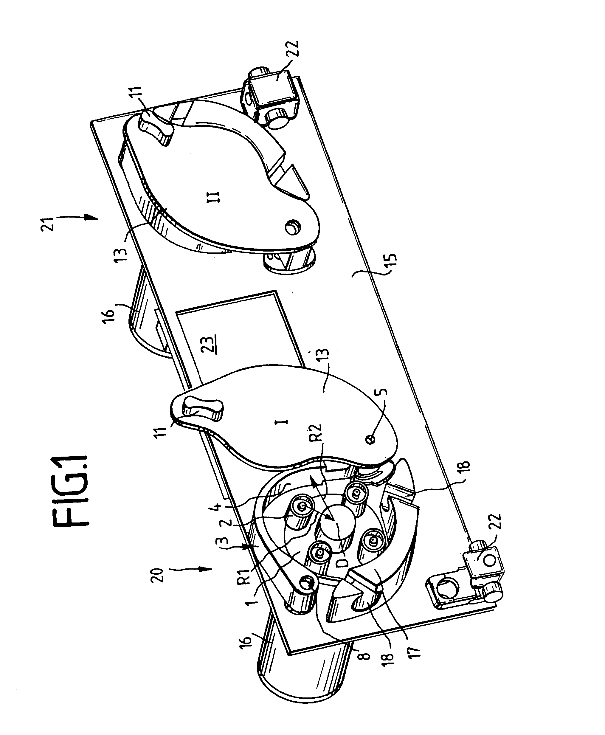
[0010] FIG. 1: perspective representation of the front plate of the device housing for two peristaltic hose pumps, without inserted flexible hoses, whereby the left hose pump is open and the right hose pump is closed;

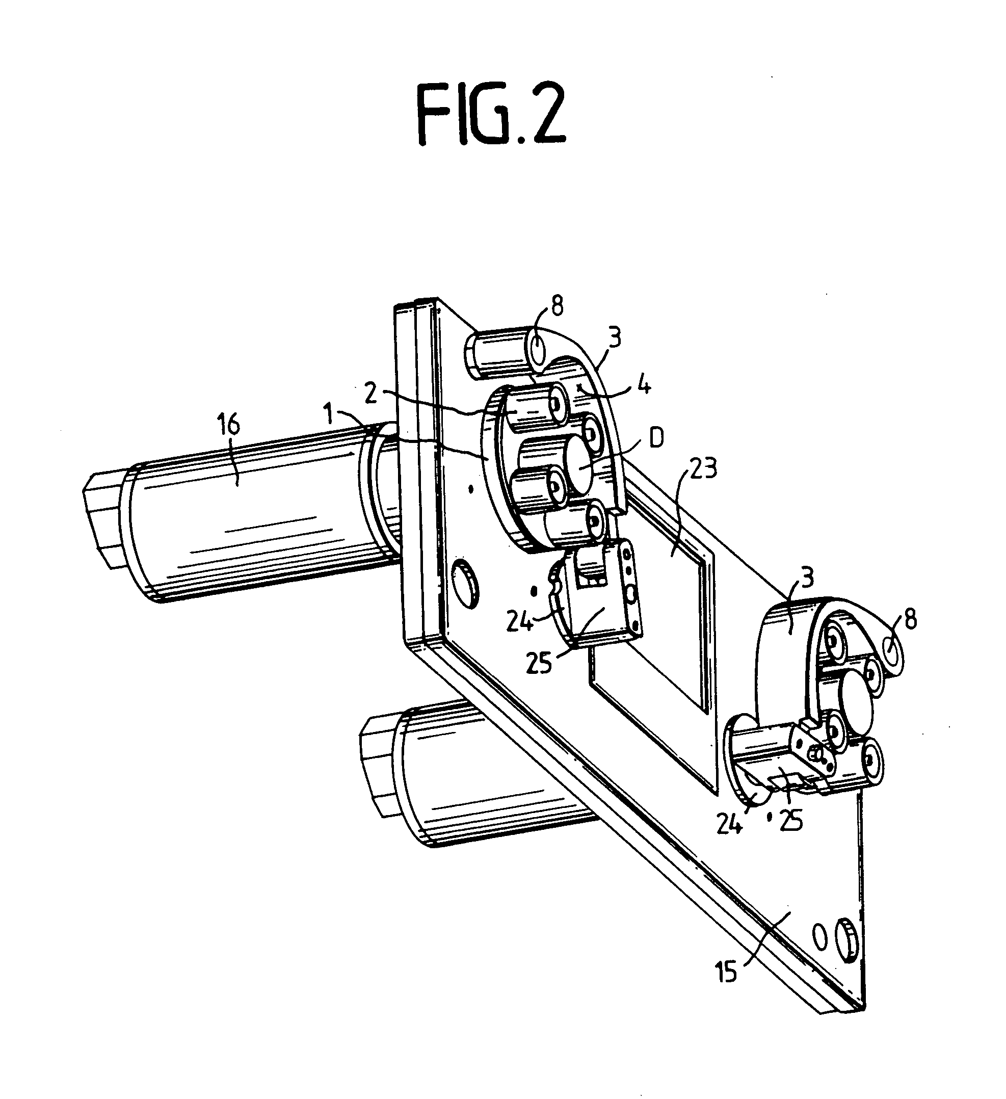
[0011] FIG. 2: perspective representation of the front plate according to FIG. 1, without the covers for the two hose pumps;

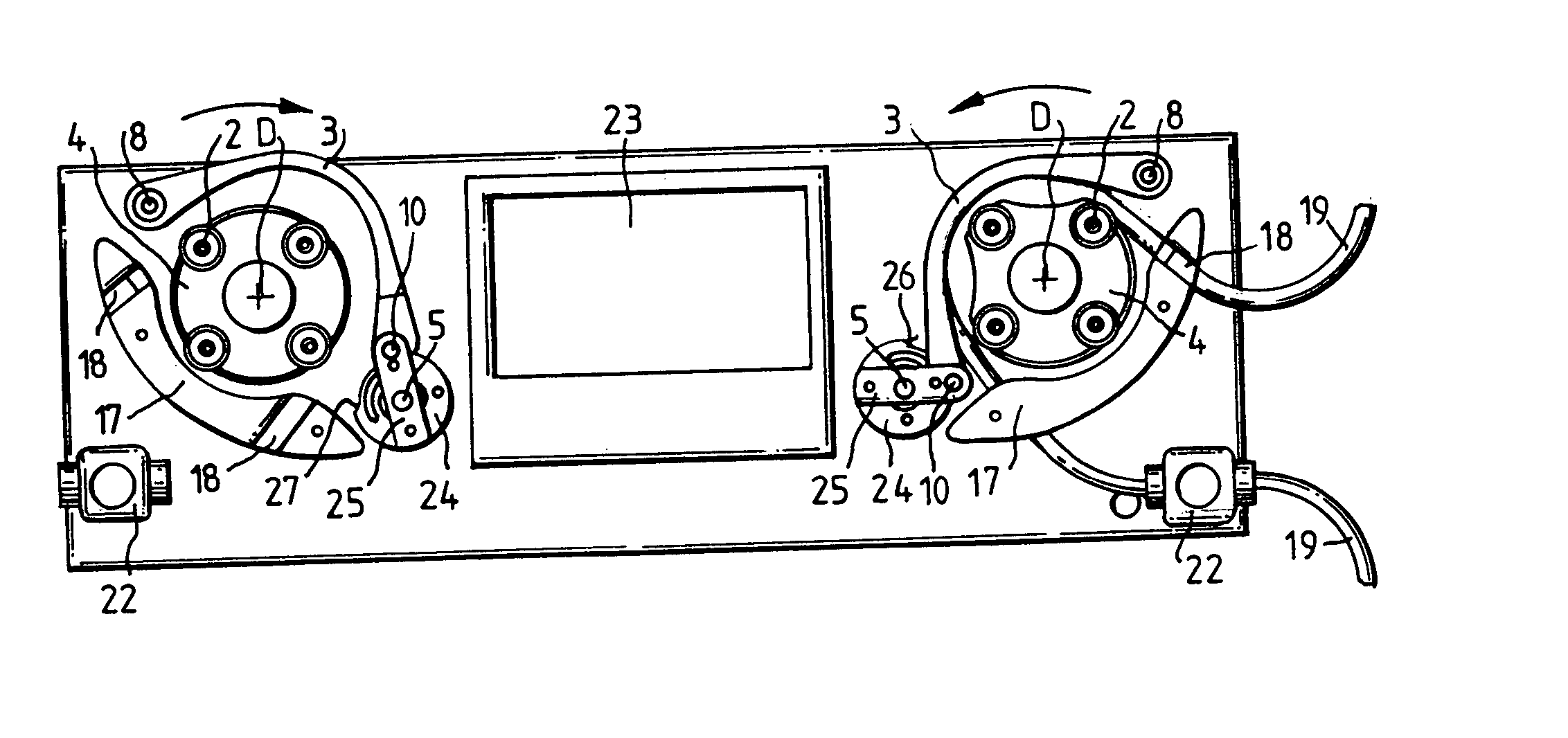
[0012] FIG. 3: top view of the representation shown in FIG. 2, with an inserted hose;

[0013] FIG. 4: perspective front view of the pressure arched element of a hose pump, and

[0014] FIG. 5: perspective rear view on to the pressure arched element with clamping disk.

[0015] FIGS. 1 through 3 show the front plate 15 of a device housing for two peristaltic hose pumps 20, 21, whose roller wheels 1 are each equipped with four rollers 2 and are driven by electric motors 16 mounted on the rear side of the front plate 15....


PUM


Abstract

The invention relates to a peristaltic hose pump comprising a roller wheel (1), which can rotate about a roller wheel axis D and which has rollers (2) that are mounted on the roller wheel (1). The rollers (2) roll away on a circular path having a radius R1 with regard to the roller wheel rotation axis D. The peristaltic hose pump also comprises a pressure arched element (3) with a supporting surface (4), whereby the supporting surface (4) extends along a circular path having a radius R2 around the rotation axis D of the roller wheel (1). In addition, a flexible hose (19) can be placed between the supporting surface (4) and the rollers (2) of the roller wheel (1). According to the invention, the supporting surface (4) is formed out of an elastically deformable synthetic material, and the pressure arched element (3) is pre-shaped with the provision that the extension of the supporting surface (4), when the pressure arched element (3) is not under tension, essentially corresponds to the extension of the supporting surface (4) when under tension.

Description

SCOPE OF THE INVENTION[0001] The invention relates to a peristaltic hose pump comprising a roller wheel, which can rotate about a roller wheel axis and which has rollers that are mounted on the roller wheel. The rollers roll along a circular path having a certain radius with respect to the roller wheel axis. The peristaltic hose pump also comprises a pressure arched element with a supporting surface, whereby the supporting surface extends along a circular path having a certain radius around the rotation axis of the roller wheel. In addition, a flexible hose can be inserted between the supporting surface and the rollers of the roller wheel.STATE OF THE ART[0002] A peristaltic hose pump of the aforementioned design is known from DE-G 83 29 579. Here the pressure arched element is formed by a deformable band, the one end of which is firmly clamped, while its other end is adjustably held in its axial direction, which facilitates the adaptation to different hose diameters. The band made ...

Claims


Application Information

Patent Timeline
IPC IPC(8): F04B43/12
CPCF05C2225/00F04B43/1284
Inventor HASER, CHRISTIANZENTNER, PETER
Owner W O M WORLD OF MEDICINE GMBH
Learn More