Metallic component for high-pressure applications

a technology of high-pressure applications and components, which is applied in the direction of fuel injecting pumps, machines/engines, manufacturing tools, etc., can solve the problems of limited local stress peak in the component, and achieve the improvement of high-pressure consistency, high-pressure consistency, and the range of admissible internal pressur

Active Publication Date: 2015-11-24
ROBERT BOSCH GMBH
View PDF13 Cites 1 Cited by
  • Summary
  • Abstract
  • Description
  • Claims
  • Application Information

AI Technical Summary

Benefits of technology

[0004]The inventive metallic component has the advantage that the high pressure consistency is improved. Said high pressure consistency can particularly be improved at geometrically unfavorable locations, and therefore local stress peaks are limited in the component. In so doing, the range for the admissible internal pressure can be enlarged, whereby durability is improved and / or the maximally achievable delivery pressure is increased.

Problems solved by technology

Said high pressure consistency can particularly be improved at geometrically unfavorable locations, and therefore local stress peaks are limited in the component.

Method used


Image

  • Metallic component for high-pressure applications
  • Metallic component for high-pressure applications
  • Metallic component for high-pressure applications

Examples


Embodiment Construction

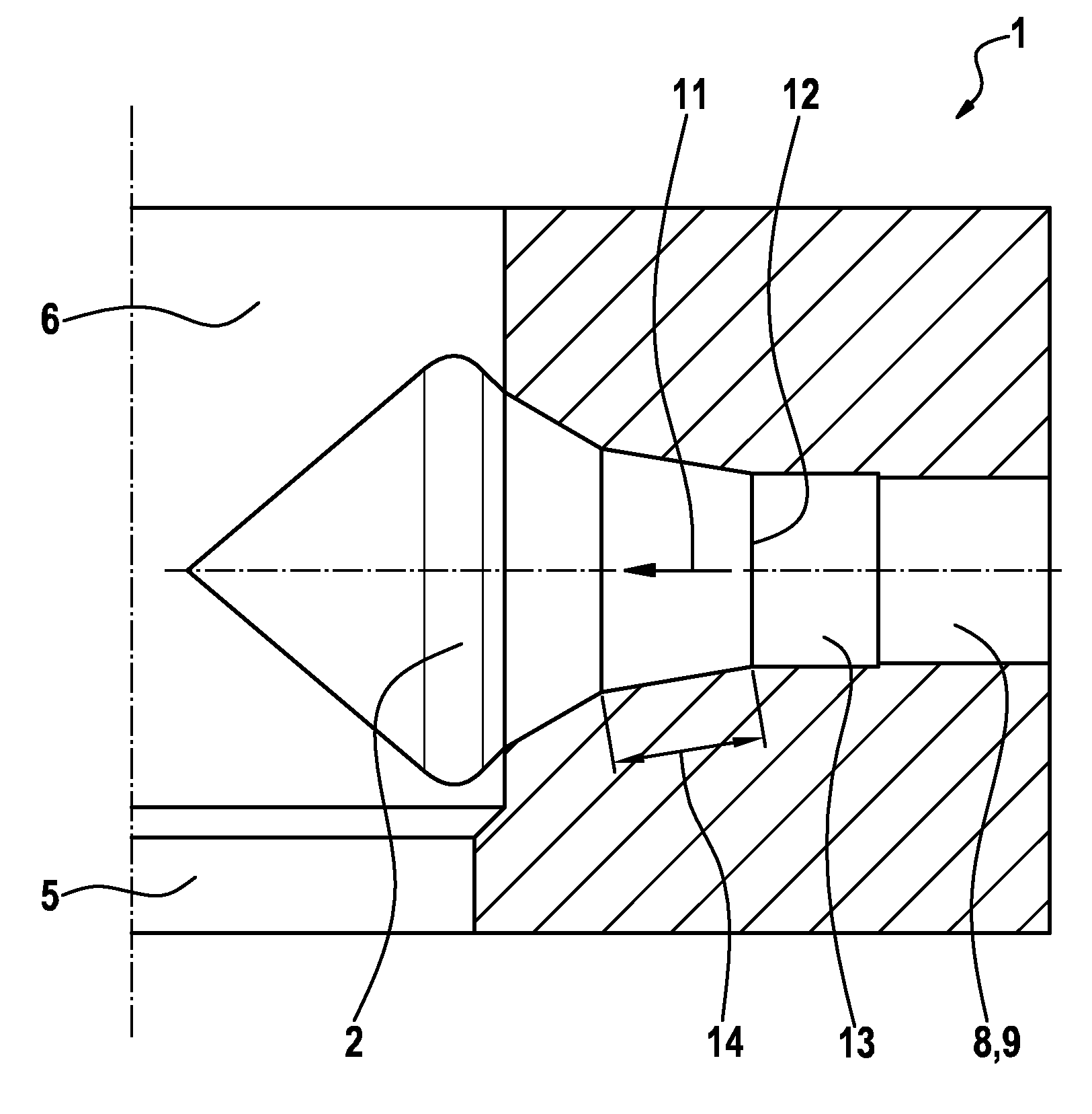
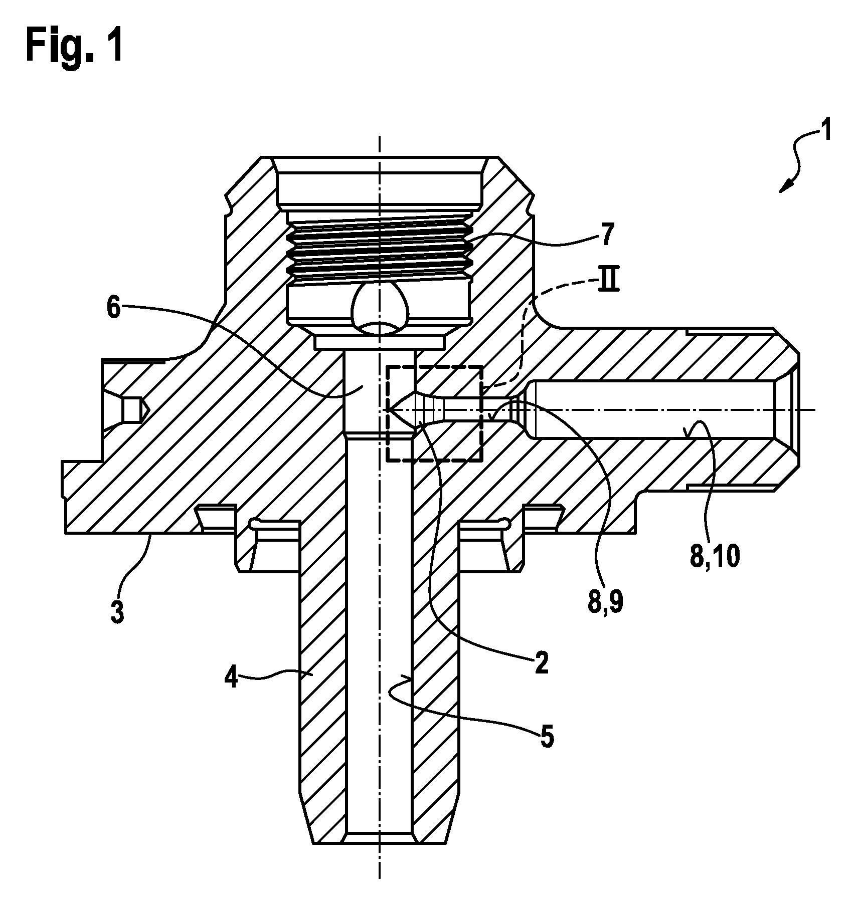
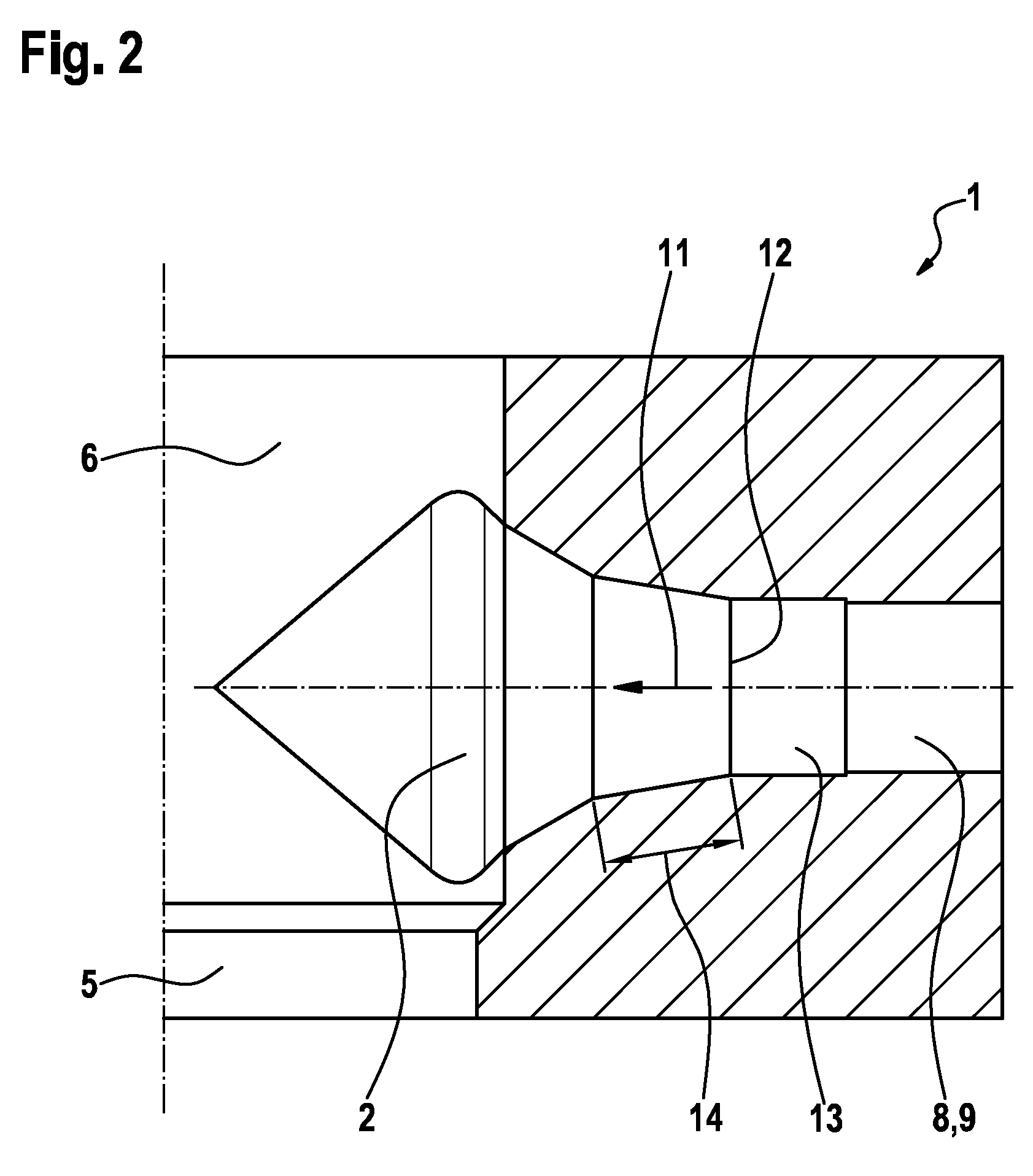
[0019]FIG. 1 shows a metallic component 1 in a schematic, axial cross-sectional view according to one exemplary embodiment of the invention. The metallic component 1 is designed as a cylinder head for a high-pressure pump in said exemplary embodiment. The metallic component 1 has a transition region 2. The design of the transition region 2 can however also be implemented in a corresponding manner in other metallic components, which particularly are designed as a fuel distributor rail or as a component for an injector. Such a metallic component is particularly suitable for fuel injection systems of air compressing, self-igniting internal combustion engines. This is the case because operational demands resulting from high interior pressures occur in components associated with such systems. The metallic component 1 according to the invention is however also suited for other applications.

[0020]The metallic component 1 of the exemplary embodiment has a side 3. In the region of side 3, th...


PUM

PropertyMeasurementUnit
pressuresaaaaaaaaaa
pressureaaaaaaaaaa
roughnessaaaaaaaaaa

Abstract

A metallic component (1) for high-pressure applications, which serves in particular for fuel injection systems of air-compressing, self-igniting internal combustion engines, comprises at least one transition region (2). The transition region (2) is re-worked here after a hardening operation. The re-working is performed by electrochemical removal and mechanical removal, in particular honing.

Description

BACKGROUND OF THE INVENTION[0001]The invention relates to a metallic component for high-pressure applications, in particular for fuel injection systems of air-compressing, self-igniting internal combustion engines.[0002]A high-pressure pump for a fuel injection device of an internal combustion engine is known from the German patent publication DE 10 2004 028 999 A1. The known high-pressure pump comprises a pump element, which has a pump piston that is guided such that it can be moved in a reciprocating manner in a cylinder bore of a pump housing part. The pump piston delimits thereby a pump working chamber in the cylinder bore. The pump working chamber can be filled with fuel via a suction valve during the intake stroke. The pump working chamber additionally has a connection to an outlet via a fuel drainage channel running inside the pump housing, said outlet being connected, for example, to a high-pressure accumulator. An exhaust valve which opens out of the pump working chamber is...

Claims


Application Information

Patent Timeline
Patent Type & Authority Patents(United States)
IPC IPC(8): B23H9/10B23H9/00B23H5/06B23H3/00F02M59/44
CPCB23H5/06B23H3/00B23H9/00B23H9/10F02M59/445F02M2200/02
Inventor GENTE, ARNOLDBURGER, CHRIS
Owner ROBERT BOSCH GMBH
Why Eureka
Try Eureka