
Eureka
For R&D, Eureka makes reading and utilizing patents & technical documents easy.
Eureka AIR
Designed for self-driven R&D workflows. Generate viable solutions, solve complex R&D challenges, empower your innovation with AI.

Eureka Materials
Designed for material experts only. Revolutionize your material R&D, from search, analyze, to developing new materials.

TechResearch
Generate reliable direction feasibility study reports for your R&D in just a few steps.

TechSeek
Discover and master advanced knowledge NOW. Basics, ideas, possibilities, all at once.

TechMind
As an expert in R&D Theories, TechMind can generates customized viable solutions instantly.

TechRisk
Analyze your overall solution with one click, know your potential R&D risks in advance.

TechMonitor
Get weekly tech updates, stay abreast of the latest tech innovations and key insights.
Steering system
- Summary
- Abstract
- Description
- Claims
- Application Information
AI Technical Summary
Problems solved by technology
Method used
Image

Examples
Embodiment Construction
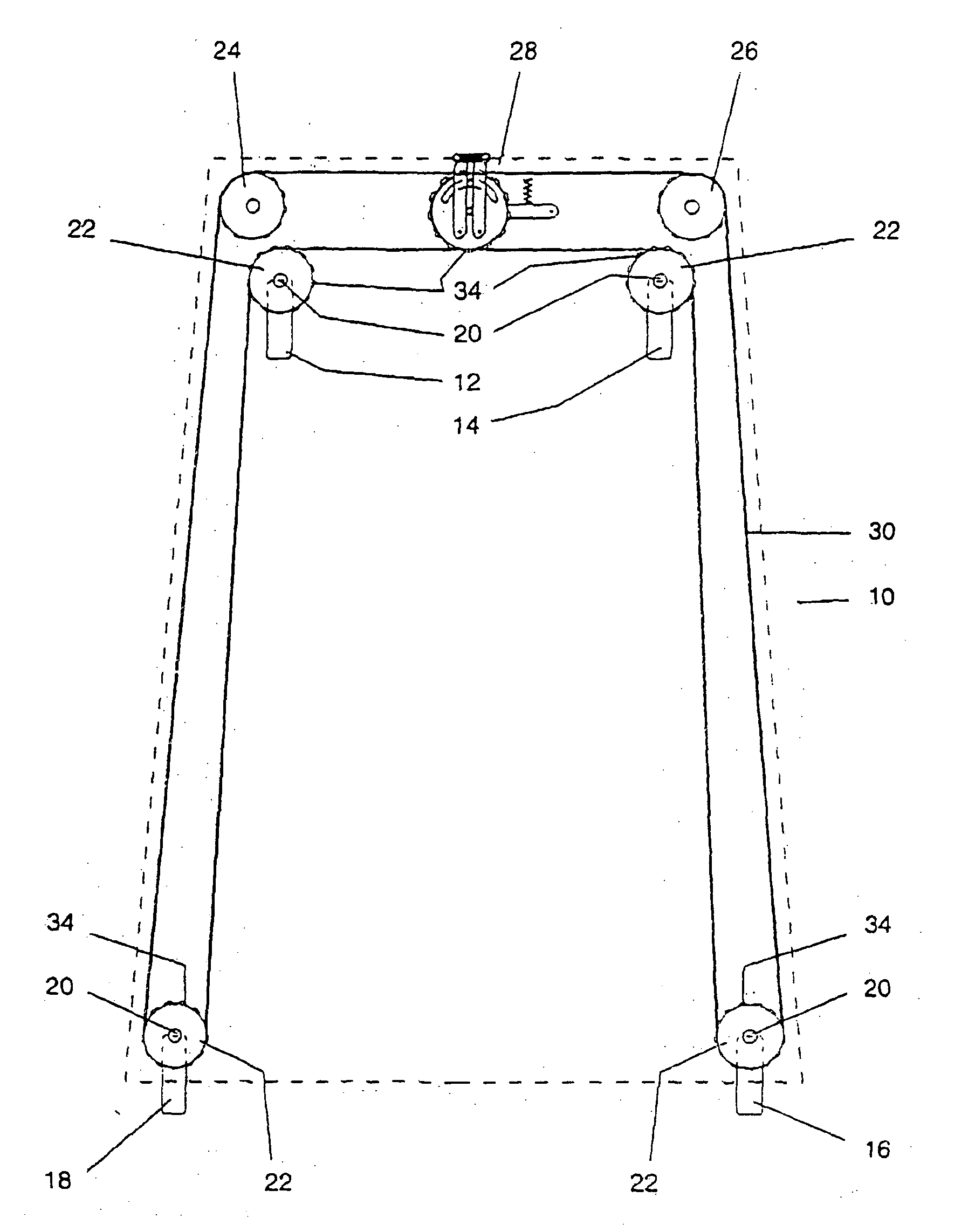
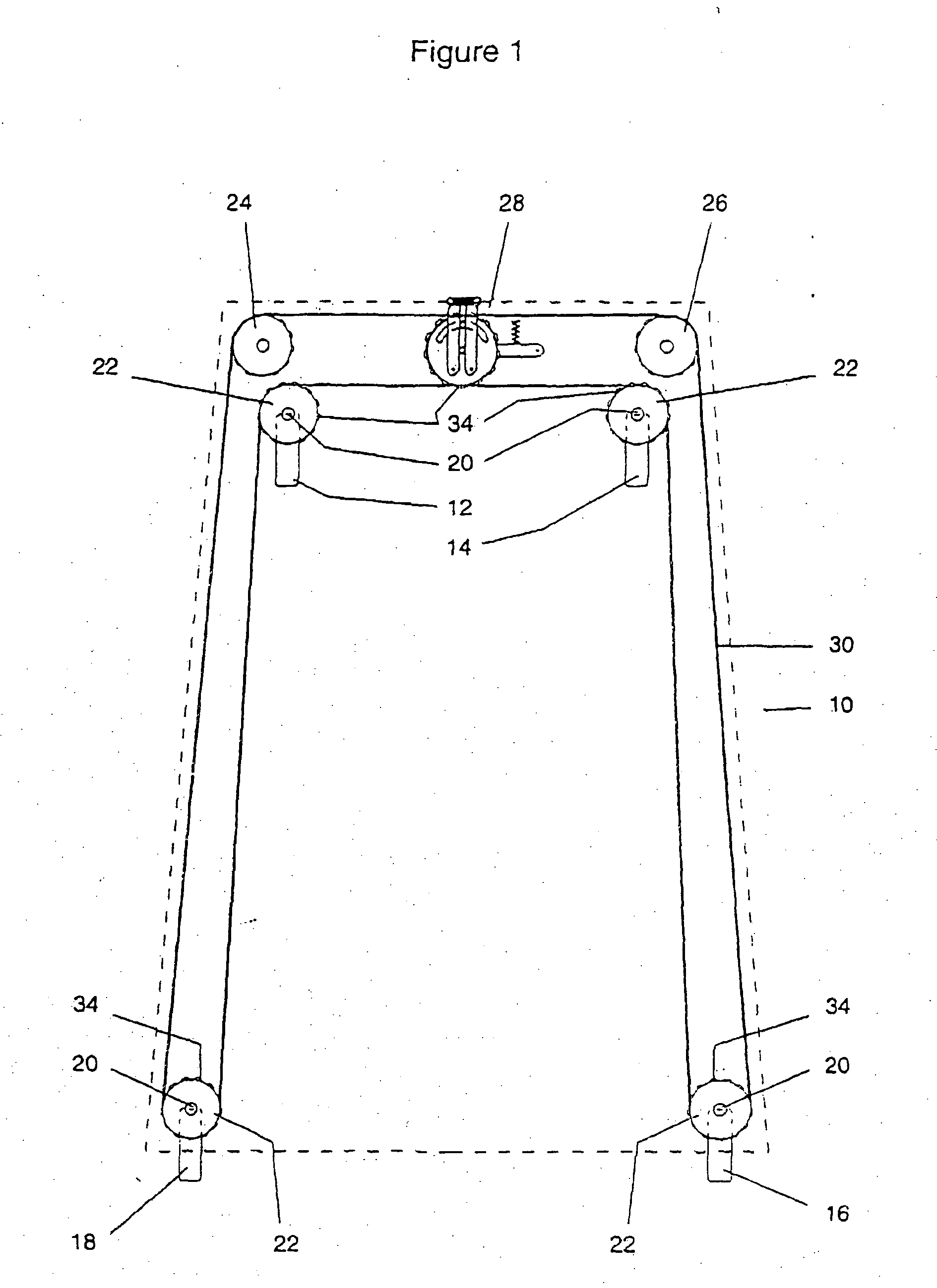
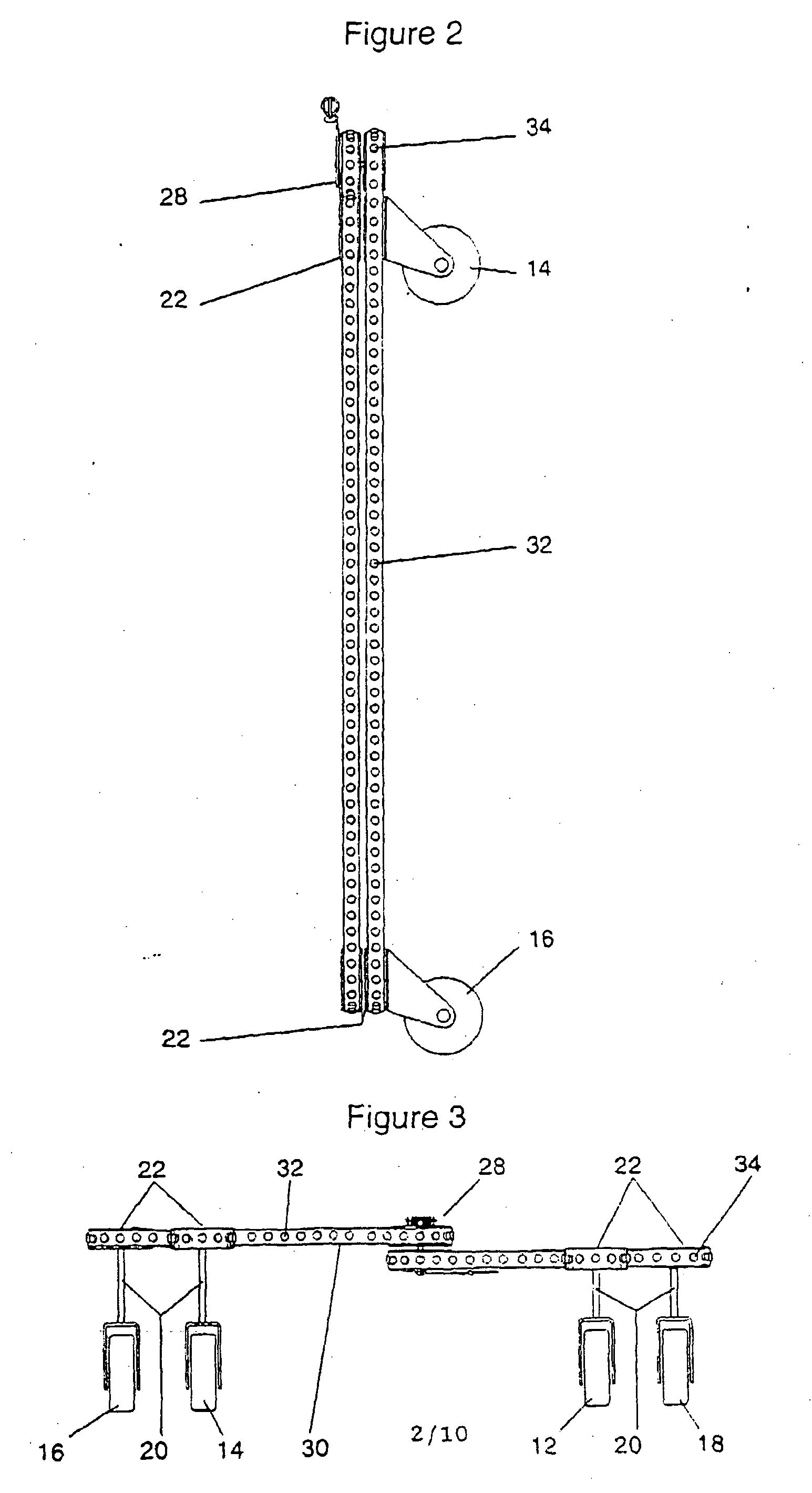
[0027] To refer firstly to FIGS. 1, 2 and 3 there is shown a vehicle generally designated as 10 and which in this instance is to represent a common device such as a supermarket trolley.
[0028] The vehicle 10 has four wheels 12, 14, 16 and 18 each mounted on a vertical swivel or castor axle 20 and which is concentric with and attached to a gear or drum 22. Two further idler gears 24, 26 are provided. A compensating means generally designated as 28 is also included. A continuous belt 30 passes around the gears 22, 24, 26 as well as the compensating means 28 (as will be described below) such that a four-wheel steering is created in accordance with our earlier Application.
[0029] The belt 30 is preferably a form of belt having a number of evenly-spaced openings 32 along its length, with the gears 22, 24, 26 having projections 34 to engage in openings 32 so that the belt 30 can drive gears 22, 24, 26, and via versa. In this way, rotation of any one wheel 12, 14, 16, 18 about its castor axl...
PUM
 Abstract
Description
Claims
Application Information
 - R&D Engineer
- R&D Manager
- IP Professional
- Industry Leading Data Capabilities
- Powerful AI technology
- Patent DNA Extraction
Browse by: Latest US Patents, China's latest patents, Technical Efficacy Thesaurus, Application Domain, Technology Topic, Popular Technical Reports.
© 2024 PatSnap. All rights reserved.Legal|Privacy policy|Modern Slavery Act Transparency Statement|Sitemap|About US| Contact US: help@patsnap.com