Method and apparatus for transferring data between data buses

a technology for data buses and data transfers, applied in logic circuits, pulse techniques, instruments, etc., can solve problems such as increasing costs, reducing reliability, and increasing pin counts

Inactive Publication Date: 2004-04-01
AVAGO TECH INT SALES PTE LTD
View PDF5 Cites 5 Cited by
  • Summary
  • Abstract
  • Description
  • Claims
  • Application Information

AI Technical Summary

Problems solved by technology

While the bi-directional voltage level shifter serves the function of translating voltage levels between two data buses, a problem arises as circuits attempt to add more components to increase functionality.
The increase in pin counts due to the addition of components increases costs and decreases reliability as more pins provide potential for additional faults and may require the use of larger, more costly custom programmable integrated circuits.
The additional latch device also increases circuit size and pin count, further increasing costs and decreasing reliability.
Furthermore, the LEDs consume power inefficiently and increase operating costs of the circuit.

Method used


Image

  • Method and apparatus for transferring data between data buses
  • Method and apparatus for transferring data between data buses
  • Method and apparatus for transferring data between data buses

Examples


Embodiment Construction

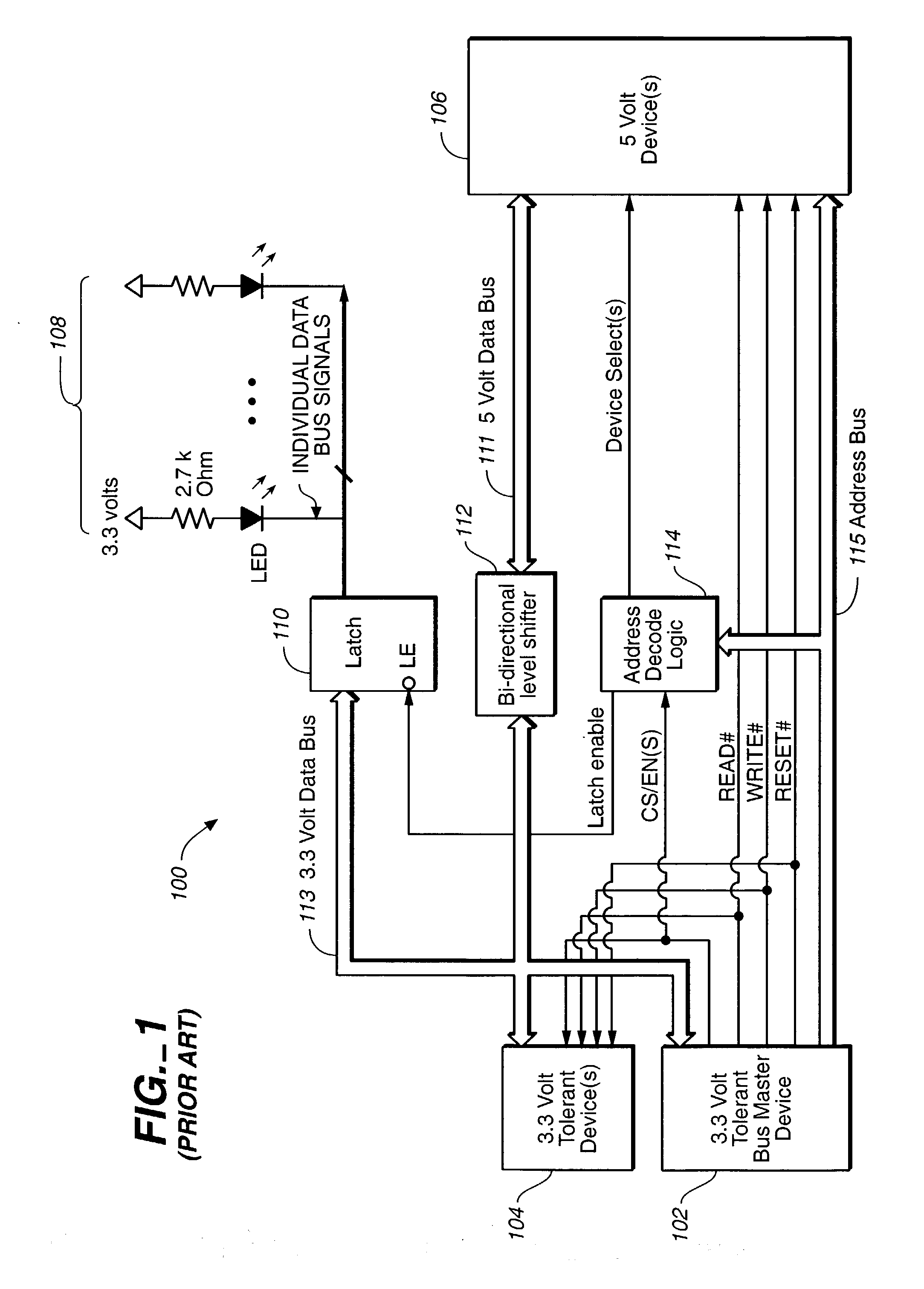
[0028] FIG. 1 is a block diagram illustrating a prior art circuit for transferring data between data buses.

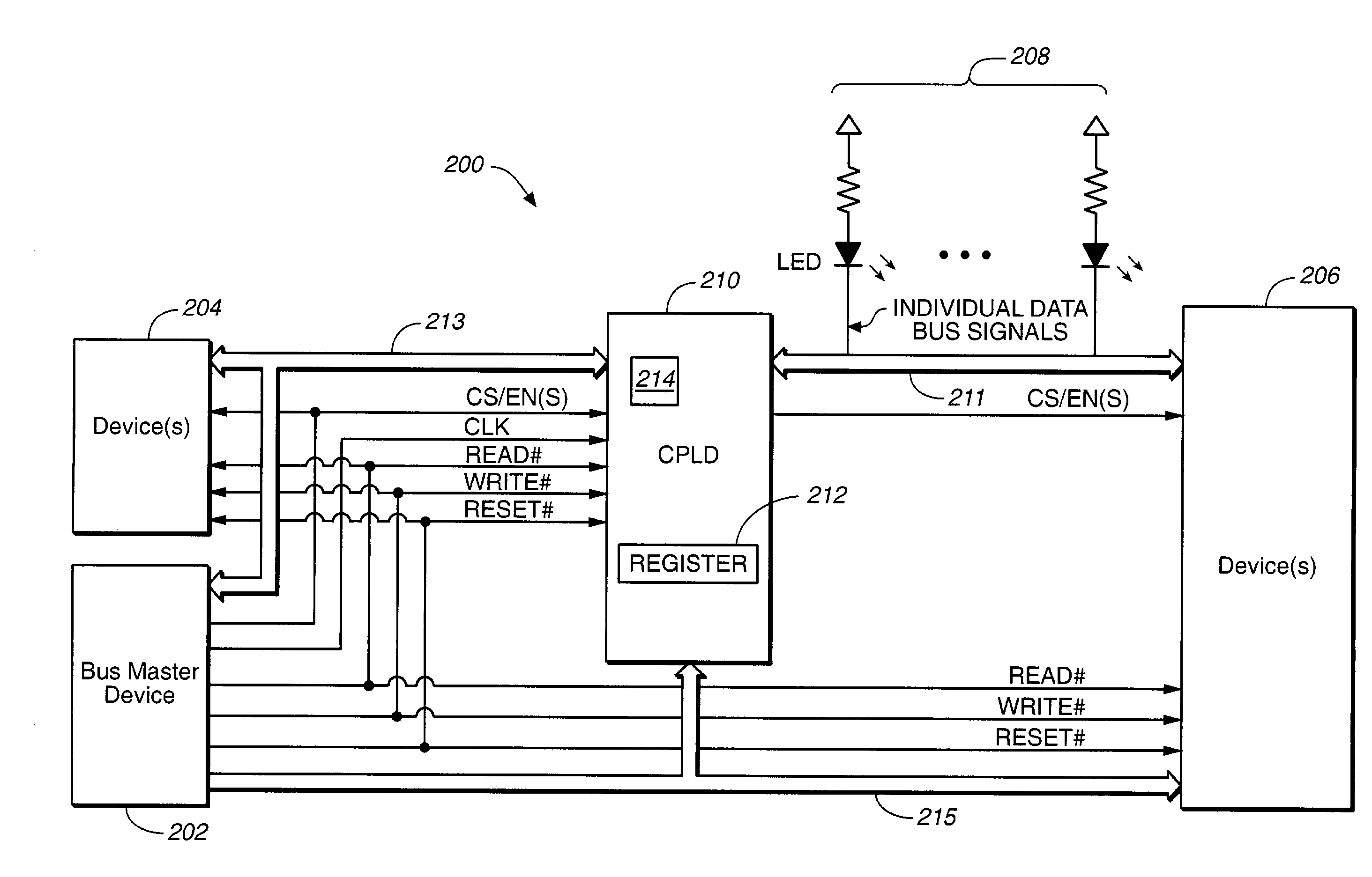
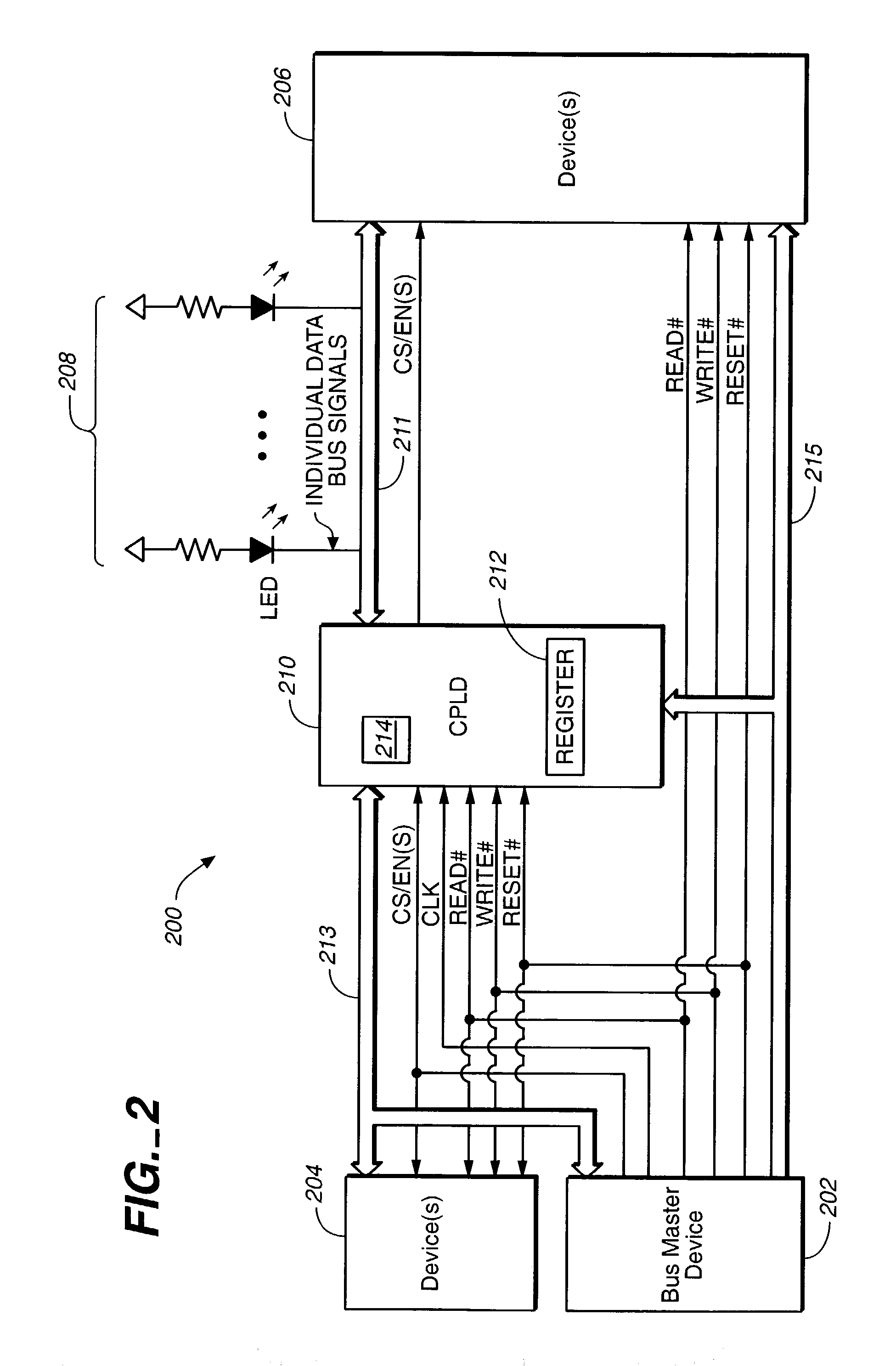
[0029] FIG. 2 is a block diagram illustrating an exemplary preferred system of the invention.

[0030] FIG. 3 is a flow chart diagram illustrating an exemplary preferred operation of the invention.

[0031] FIG. 4 is a flow chart diagram illustrating an exemplary preferred step of the operation of the invention.

[0032] With reference now to the figures, a prior art circuit for transferring data of differing voltage levels between data buses 113 and 111 is shown in circuit 100. Circuit 100 includes 3.3V tolerant bus master device 102, 3.3V tolerant device(s) 104, 5V device(s) 106, LED(s) 108, latch 110, bi-directional level shifter 112, and address decode logic 114. Bus master device 102 controls data being transferred on data bus 113 and data bus 111. When communicating to LED(s) 108, data is transferred over data bus 113 and latched to LED(s) 108 via latch 110. Latch 110 is a discret...


PUM


Abstract

Systems and methods for transferring data. A circuit transfers information between two buses using different signal voltage levels and multiplexes signals applied to the second bus over multiple devices coupled thereto. The data on a first data bus is transferred at a first voltage level and the data on a second data bus is transferred at a second voltage level. For example, the first data bus may transfer data at 3.3V and the second data bus may transfer data at 5V. A logic device (e.g., a CPLD) is connected between the first and the second data buses for transferring the data between the first and second voltage levels. The logic device is also configured for multiplexing the data with the second voltage level between first and second devices (e.g., one or more LEDs and/or NVSRAMs) connected to the second data bus.

Description

[0001] 1. Field of the Invention[0002] The present invention is generally directed toward transferring data of multiple voltage levels between data busses. More specifically, the invention relates to transferring data between devices on a first data bus and a second data bus where the data buses use different signal voltage levels and where the second bus utilizes multiplexing structures to apply data to each of multiple devices coupled thereto.[0003] 2. Discussion of Related Art[0004] Many circuit components transfer data between one another. Typically, the circuit components transfer the data through a data bus when parallel communications are desired. Some circuit components operate on voltages that differ from operating voltages of the other components. To ensure the voltage tolerances of each component are not breached, the components are often grouped according to operating voltage levels. Each group of components is connected to a data bus that serves a particular operating v...

Claims


Application Information

Patent Timeline
Patent Type & Authority Applications(United States)
IPC IPC(8): G06F13/42
CPCG06F13/423
Inventor MCCOLLUM, JUSTIN RANDOLPHPIPER, STEPHEN SCOTTHEAD, DAVID MICHAEL
Owner AVAGO TECH INT SALES PTE LTD
Why Eureka
Try Eureka