Altering surface of display screen from matt to optically smooth

Inactive Publication Date: 2004-04-08
APTIV TECH LTD
View PDF1 Cites 104 Cited by
  • Summary
  • Abstract
  • Description
  • Claims
  • Application Information

AI Technical Summary

Benefits of technology

0048] The present invention also has a number of other advantages including the creation of images with improved clarity with a wide angle of view, but without requiring the production of expensive customised screens.
0049] This invention allows all the necessar

Problems solved by technology

When viewing a large number of visual elements, certain variations or properties in the visual characteristics of elements can lead to rapid detection by preattentive processing.
This timeframe is insufficient for a human to consciously decide to look at a different portion of the scene.
However, if the target is composed of a conjunction of unique features, i.e. a conjoin search, then research shows that these may not be detected preattentively.
Using the above examples, if a target is comprised for example, of a red circle set within distractors including blue circles and red squares, it is not possible to detect the red circle preattentively as all the distractors include one of the two unique features of the target.
In comparison, if the constituent elements of the above described cubes are reorientated to remove the apparent three dimensionality, subjects cannot preattentively detect targets which have been inverted for example.
However, further problems occur with the introduction of this extra element.
Bi-refr

Method used


Image

  • Altering surface of display screen from matt to optically smooth
  • Altering surface of display screen from matt to optically smooth
  • Altering surface of display screen from matt to optically smooth

Examples


Embodiment Construction

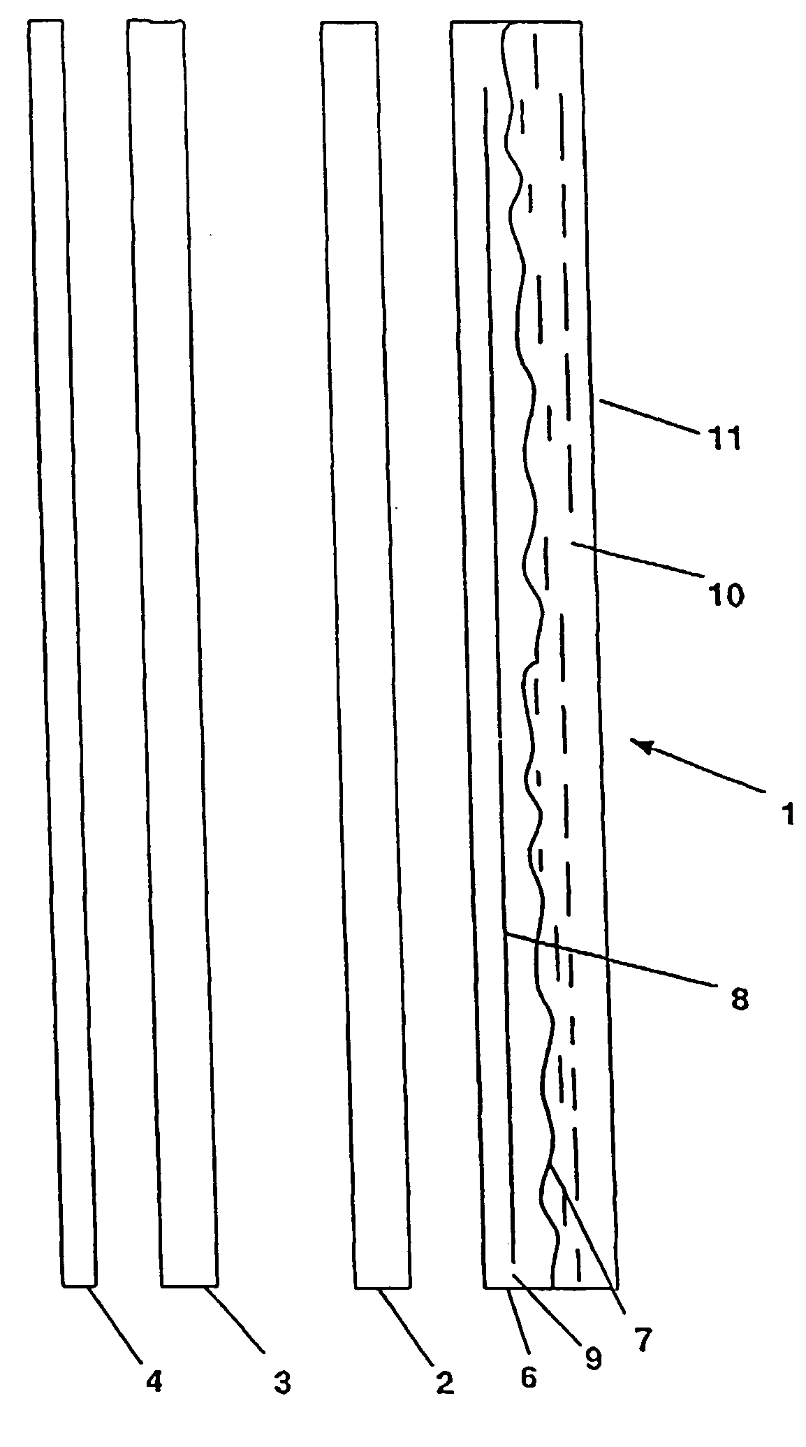
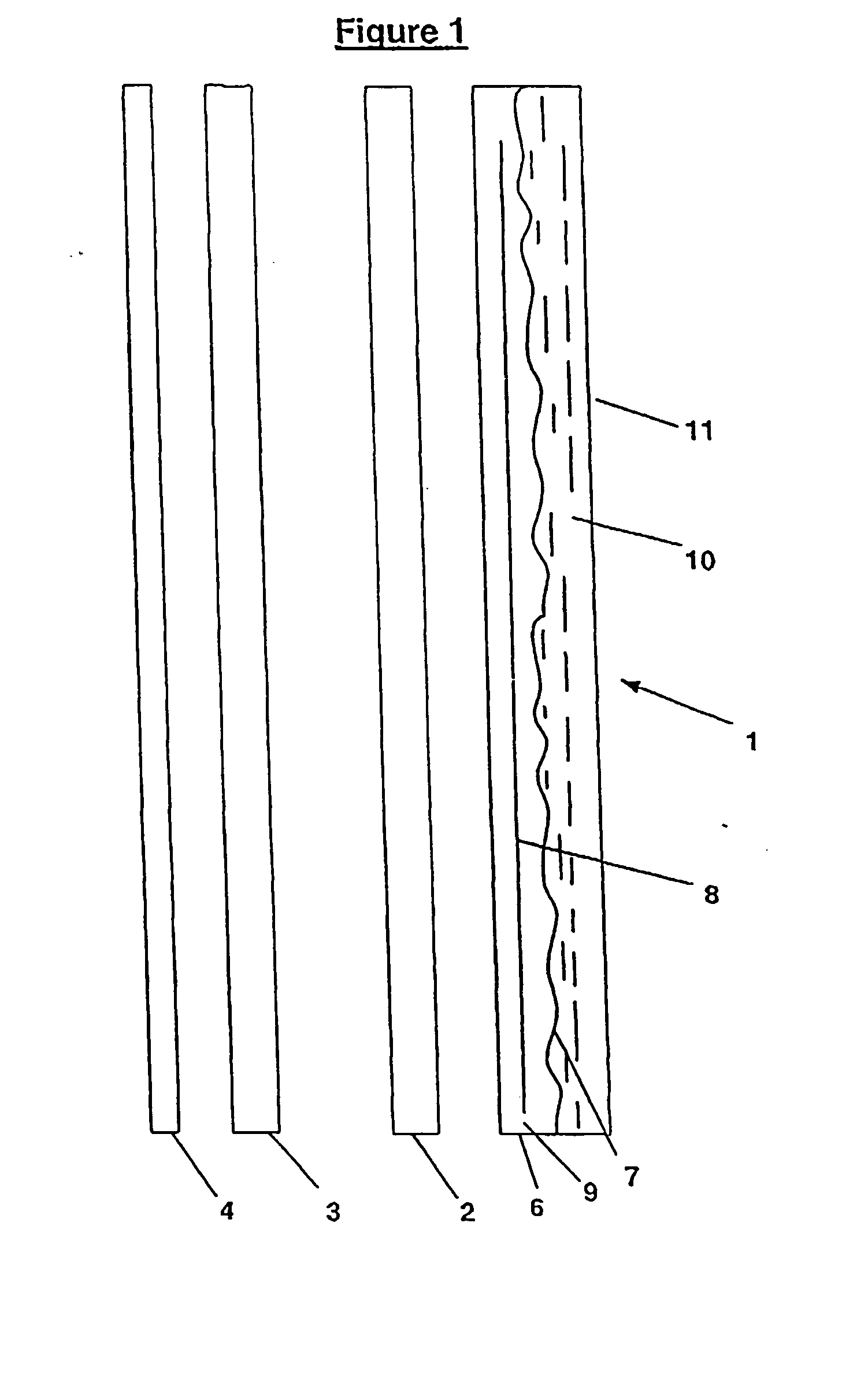
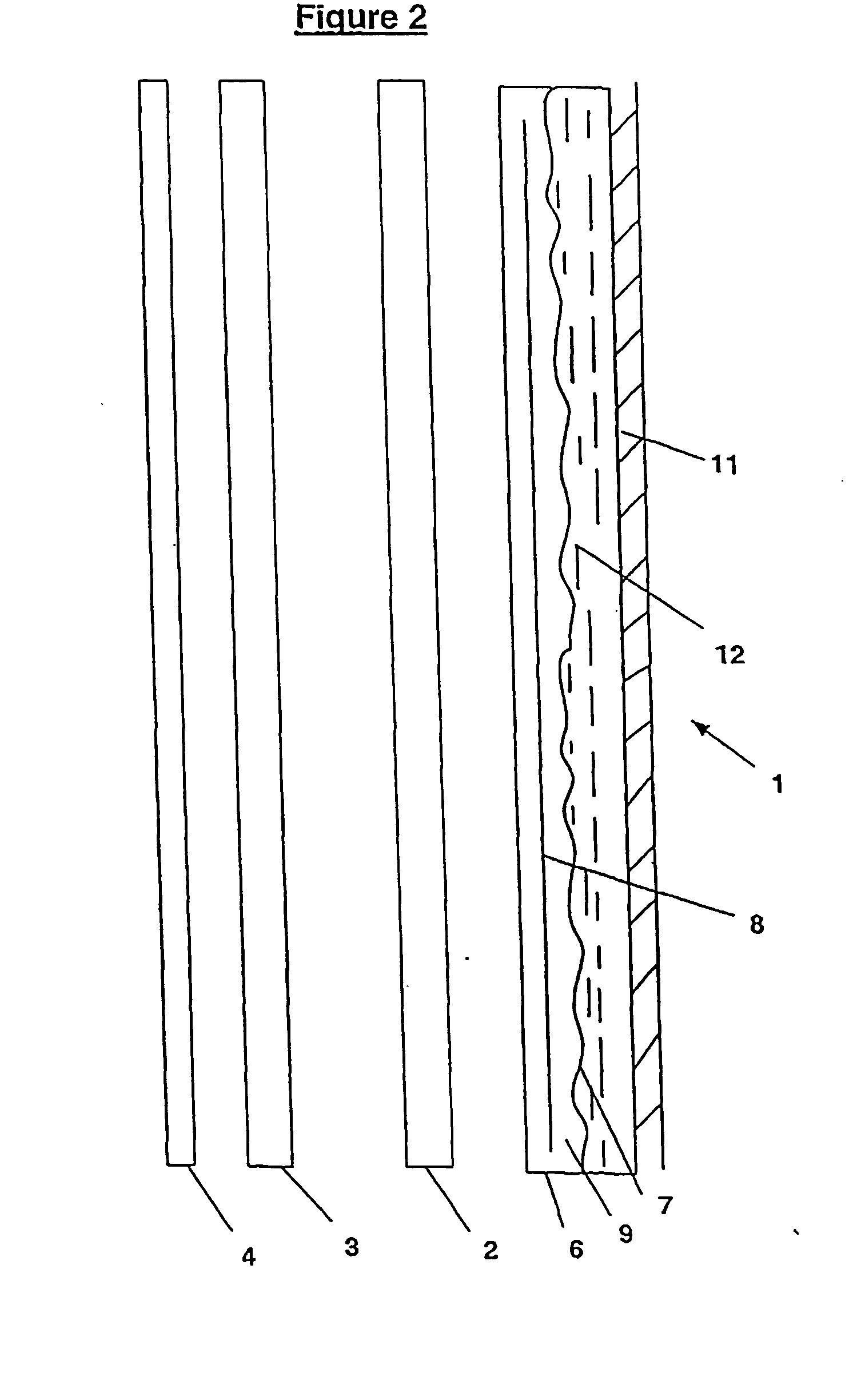
[0054] The FIGS. 1-3 illustrate preferred embodiments of the present invention implemented with a dual screen display (1) composed of a plurality of transparent imaging screens in the form of a front LCD screen (2), parallel to, but spaced apart from a rear display screen (3) provided with a backlight (4).

[0055] It should be apparent to one skilled in the art that a number of alternative display technologies may be utilised in place of the LCD screens. Furthermore, although FIG. 1 shows a single screen (2) in front of the rear display (3) for the sake of clarity and convenience, any number of additional (at least partially transparent) imaging screens (2) may be incorporated. Although the rear screen (3) may also be an LCD screen, it will be apparent that alternative, non-transparent display technology may be employed.

[0056] Such displays provide a three dimensional quality the scene viewed by an observer, as described in the applicants co-pending patents PCT No. PCT / NZ98 / 00098 and ...


PUM


Abstract

A matt surface (7) of a display screen (2) is converted to an optically flat surface (11), for example, via an epoxy resin coating (10) or the like which has a refractive index equal to that or the matt surface (7). Alternatively, the matt surface (7) may be removed from the screen (2), and replaced with an optically smooth surface. The matt surface may be a diffusive surface (7) formed on a birefringent film (6) of an LCD screen (2). The display screen (2) is the front screen of a multilevel three-dimensional display comprising layered screens (2, 3), and altering the surface from matt to flat reduces the blurring of displayed images.

Description

[0001] This invention relates to improved viewing technology.[0002] In paticular, this invention will be discussed in relation to 3-dimensional display technology such as that described in the applicant's co-pending patent application PCT / NZ0098 / 00098 and PCT / 0099 / 00021. It should be seen however, that the principles of the present invention should not be limited to this use and can be applied elsewhere, particularly to display technology whereby a viewer looks through a screen or the like to see another image in the background.[0003] Reference shall now be made to use of the present invention in relation to the technology as disclosed in the above referenced patent applications.[0004] The applicant has previously developed a 3-dimensional viewing technology. This technology uses in preferred embodiments two or more overlapping liquid crystal display (LCDs) screens positioned parallel to but spaced apart from each other. In addition to the more obvious benefits of 3-dimensional disp...

Claims


Application Information

Patent Timeline
IPC IPC(8): G02B1/10G02F1/1335G02F1/13363
CPCG02B1/10G02F1/133502Y10T428/1036G02F1/13363Y10T156/10G02F1/133528C09K2323/03
Inventor SEARLE, MARK JOHN
Owner APTIV TECH LTD
Why Eureka
Try Eureka