

Double clutch assembly
a technology of connecting assembly and double clutch, which is applied in the direction of clutches, road transportation, climate sustainability, etc., can solve the problem of difficulty in connecting the double clutch assembly using the connecting assembly
- Summary
- Abstract
- Description
- Claims
- Application Information
AI Technical Summary
Benefits of technology
Problems solved by technology
Method used
Image

Examples
Embodiment Construction
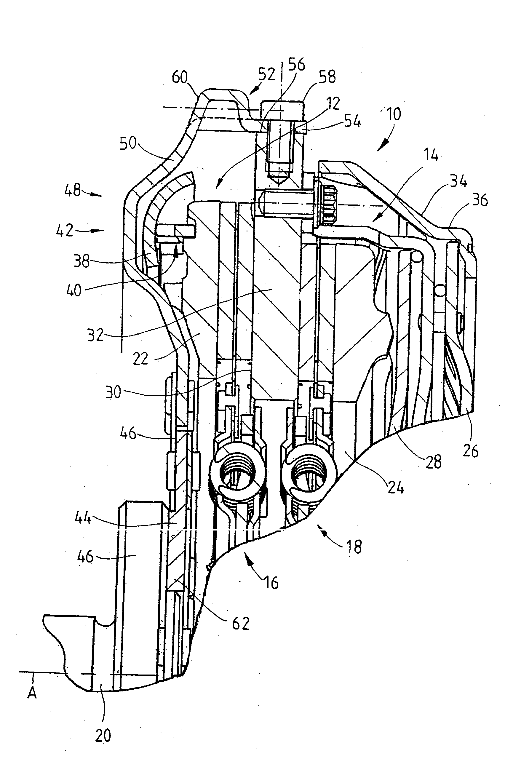
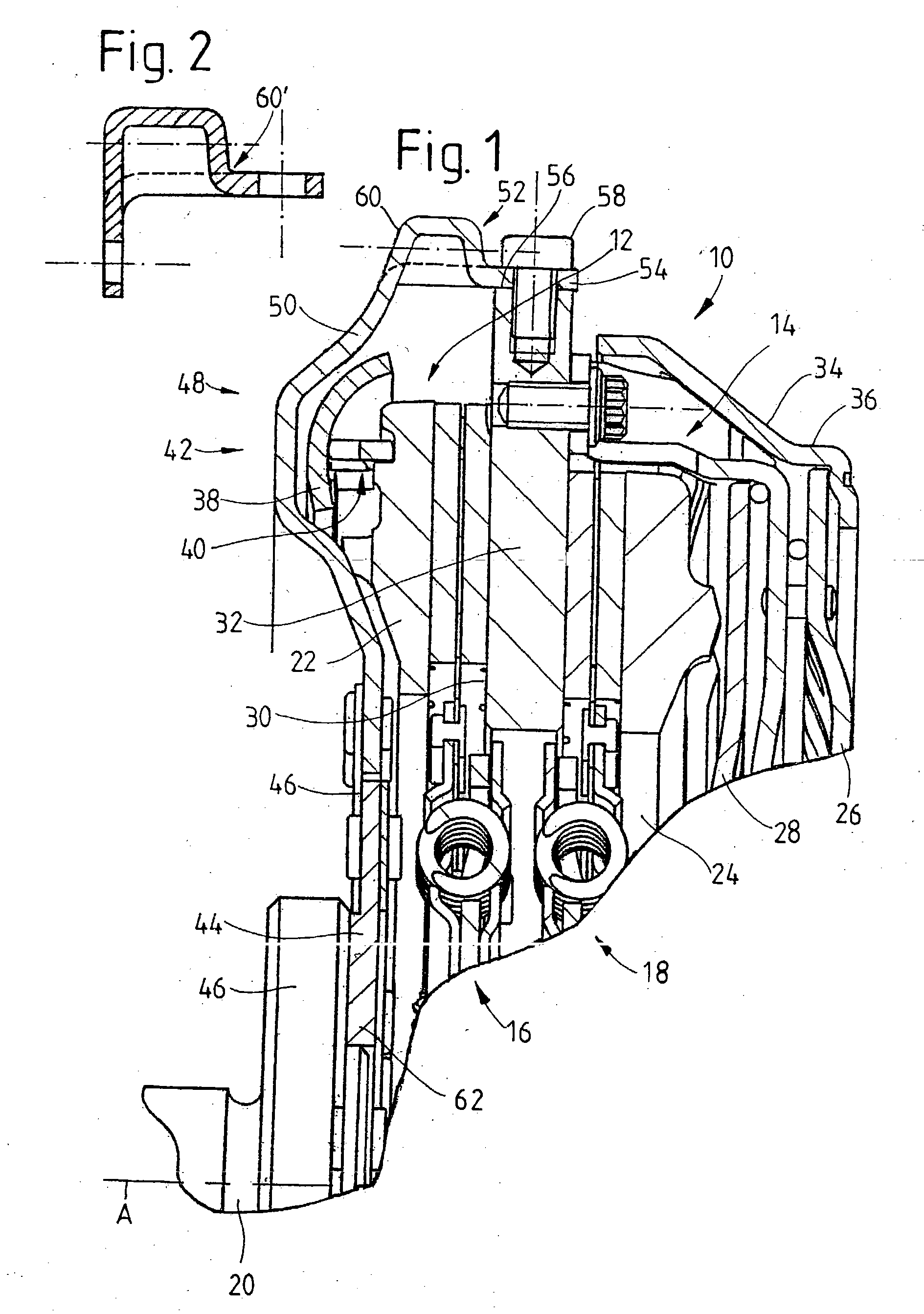
[0038] FIG. 1 shows a double clutch assembly 10 including two clutch areas 12, 14, by which either one of two transmission input shafts, i.e., either one of the two clutch disks 16 or 18 nonrotatably connected to these input shafts, can be nonrotatably connected as desired to a drive element 20, such as the crankshaft of an internal combustion engine.
[0039] Each of the two clutch areas 12, 14 comprises a pressure plate 22, 24. Each of these pressure plates can be pretensioned by the force exerted by a force-exerting assembly 26, 28 toward an intermediate plate 32, which provides an abutment assembly 30 for the two clutch areas 12, 14, so that, as a result, the clutch disks 16, 18 assigned to the clutch areas 12, 14 in question, can be clamped between the pressure plates 22, 24 and the intermediate plate 32 for the transmission of torque.
[0040] The force-exerting assemblies 26, 28 can be designed as, for example, lever assemblies, by means of which an engaging force, provided by an a...
PUM
 Abstract
Description
Claims
Application Information