Refrigeration cycle apparatus

a refrigeration cycle and cycle technology, applied in the direction of domestic cooling apparatus, lighting and heating apparatus, machine operation mode, etc., can solve the problems of deteriorating the operation efficiency of the refrigeration cycle apparatus compared with a conventional refrigerant, difficulty in maintaining the optimal cop when the operation condition is met, and increase the amount of refrigerant flowing through the bypass pip

Active Publication Date: 2004-05-06
PANASONIC CORP
View PDF6 Cites 23 Cited by
  • Summary
  • Abstract
  • Description
  • Claims
  • Application Information

AI Technical Summary

Problems solved by technology

When a temperature higher than this temperature is utilized, a high pressure side (outlet of the compressor--gas cooler--inlet of pressure reducing device) of the refrigeration cycle apparatus is brought into a supercritical state in which CO.sub.2 refrigerant is not condensed, and there is a feature that operation efficiency of the refrigeration cycle apparatus is deteriorated as compared with a conventional refrigerant.
However, when the refrigeration cycle apparatus is provided with the expander and power recover by the expander is used as a portion of a driving force of the compressor,

Method used


Image

  • Refrigeration cycle apparatus
  • Refrigeration cycle apparatus
  • Refrigeration cycle apparatus

Examples


Embodiment Construction

[0039] A refrigeration cycle apparatus according to an embodiment of the present invention will be explained with reference to the drawings below.

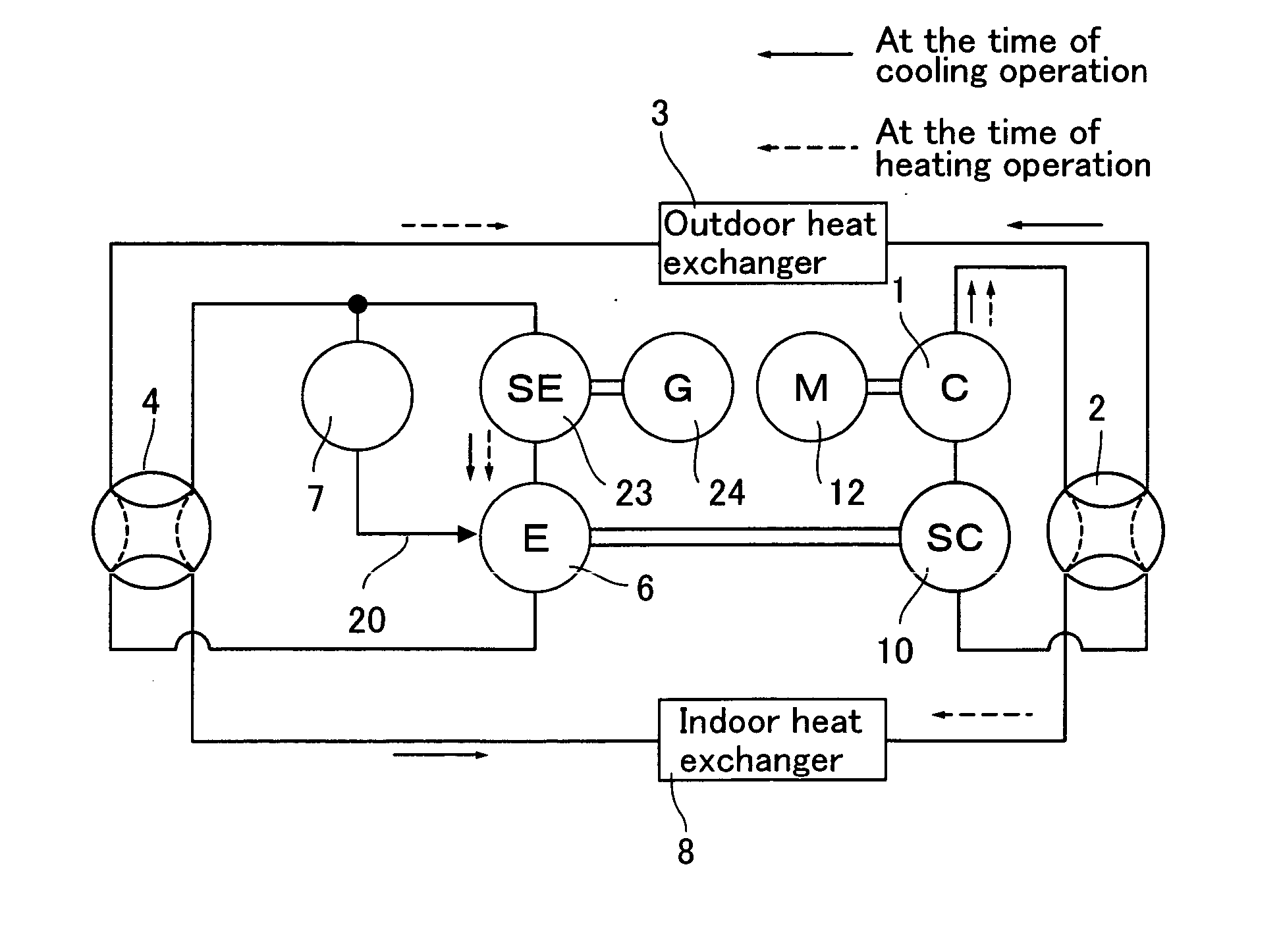
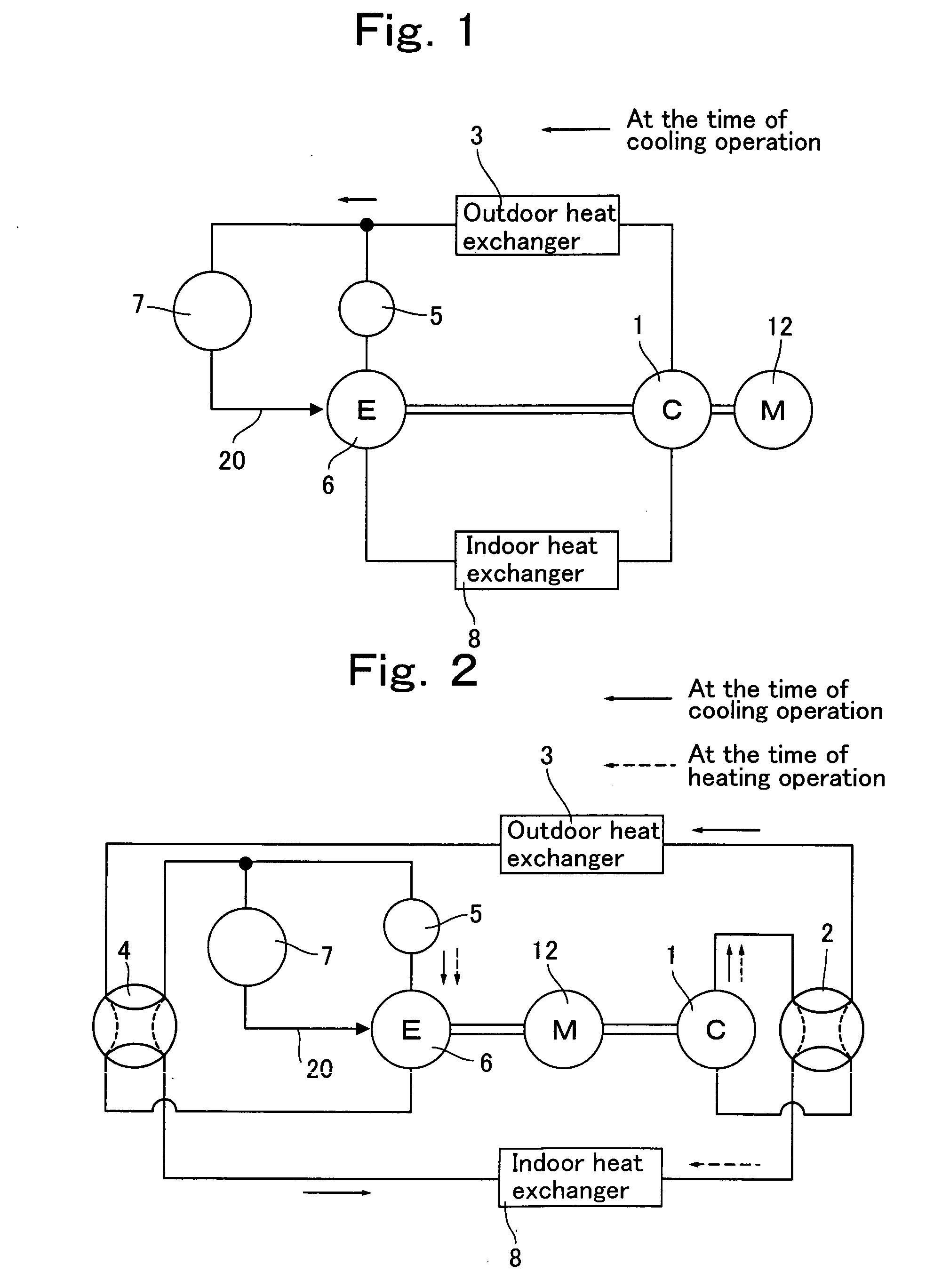
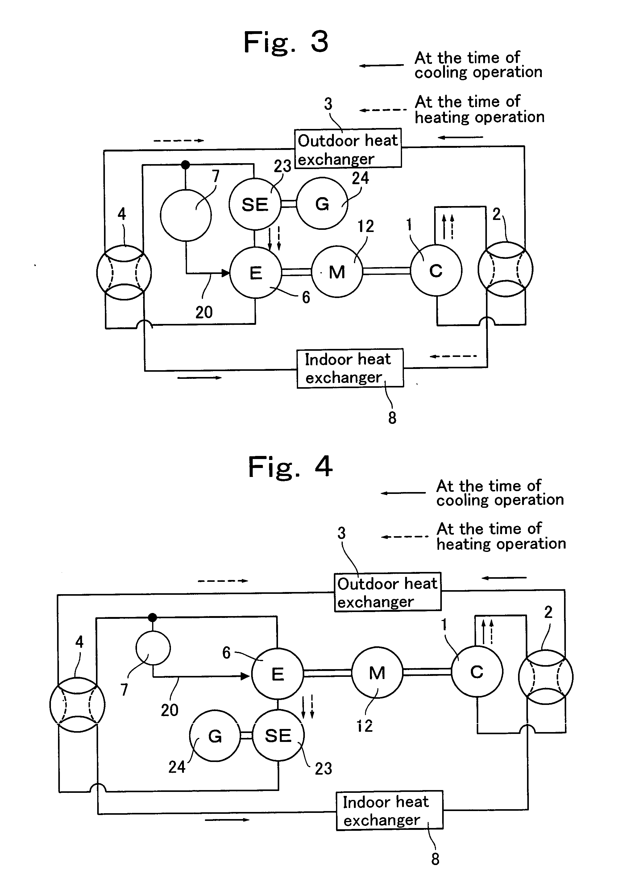
[0040] FIG. 1 shows a structure of the heat pump type air conditioner of the present embodiment.

[0041] As shown in FIG. 1, the heat pump type air conditioner of this embodiment uses CO.sub.2 refrigerant as refrigerant, and has refrigerant circuit. The refrigerant circuit comprises a compressor 1 having a motor 12, an outdoor heat exchanger 3, an expander 6 and an indoor heat exchanger 8 which are all connected to one another through pipes.

[0042] The expander 6 is provided at its inflow side with a pre-expansion valve 5.

[0043] The refrigerant circuit is provided with an injection circuit 20. The injection circuit 20 introduces high pressure refrigerant on the side of an outlet of the outdoor heat exchanger 3 in a halfway of the expansion process of the expander 6. The injection circuit 20 is provided with an adjusting valve 7 which adjusts ...


PUM


Abstract

It is an object of the present invention to reduce the constraint that the density ratio is constant as small as possible, and to obtain high power recovering effect in a wide operation range. A refrigeration cycle apparatus uses carbon dioxide as refrigerant and has a compressor, an outdoor heat exchanger, an expander and an indoor heat exchanger. An injection circuit for introducing high pressure refrigerant is provided in a halfway of an expansion process of said expander.

Description

[0001] The present invention relates to a refrigeration cycle apparatus using carbon dioxide as refrigerant and having a compressor, an outdoor heat exchanger, an expander and an indoor heat exchanger.BACKGROUND TECHNIQUE[0002] A flow rate of refrigerant which circulates through a refrigeration cycle apparatus is all the same in any points in a refrigeration cycle. If a suction density of refrigerant passing through a compressor is defined as DC and a suction density of refrigerant passing through an expander is defined as DE, the DE / DC (density ratio) is always constant.[0003] In recent years, attention is focused on a refrigeration cycle apparatus using, as refrigerant, carbon dioxide (CO.sub.2, hereinafter) in which ozone destroy coefficient is zero and global warming coefficient is extremely smaller than Freon. The CO.sub.2 refrigerant has a low critical temperature as low as 31.06.degree. C. When a temperature higher than this temperature is utilized, a high pressure side (outl...

Claims


Application Information

Patent Timeline
IPC IPC(8): F25B1/00F25B1/10F25B9/00F25B9/06F25B11/02F25B13/00F25B41/04
CPCF25B1/10F25B9/008F25B2309/061F25B13/00F25B9/06
Inventor NAKATANI, KAZUOKAWABE, YOSHIKAZUINOUE, YUJIOKAZA, NORIHOHIWATA, AKIRA
Owner PANASONIC CORP
Why Eureka
Try Eureka