Obstacle detection device and method therefor

a detection device and obstruction technology, applied in image enhancement, scene recognition, instruments, etc., can solve the problems of low detection resolution, insufficient measurement range, and erroneous detection of non-objective objects

Active Publication Date: 2004-05-20
KK TOSHIBA
View PDF9 Cites 195 Cited by
  • Summary
  • Abstract
  • Description
  • Claims
  • Application Information

AI Technical Summary

Problems solved by technology

The active sensors have, however, problems for an application of detecting any obstacles lying in the vehicles' way on the roads such as other vehicles.
Specifically, the problems are associated with low detection resolution, not enough measurement range, erroneous detection of non-obstacles on the roads, and erroneous detection of objects lying on non-disturbing road side due to no driving lane detection capability.
The issue here is that, many obstacles are actually similar to roads in brightness intensity or pattern, resulting in difficulty achieving the higher usability with the less erroneous detection.
Thus, stereoscopic views seem to be a solution for obstacle and lane detection with higher accuracy, but still bear problems.
For example, a corresponding point search cannot be uniquely solved, and the calculation cost is quite expensive.
Consequently, these methods bear such problems, due to vehicle vibration, as frequent erroneous detection especially around the texture on the road plane such as white lines, road signs, paint, road stains, shadows of roadside objects and vehicles, and the like.
As described above, with an obstacle detection device using CCD cameras of a conventional type, usage environment is limited, or the relationship between the road plane and the respective cameras continuously changes in relative position and posture due to vibrations during the device operation or driving vehicle.
As a result, frequent erroneous detection occurs especially around the texture on the road plane such as white lines, road signs, paint, road stains, shadows, and the like, considerably lowering the true detection accuracy of obstacle detection.

Method used


Image

  • Obstacle detection device and method therefor
  • Obstacle detection device and method therefor
  • Obstacle detection device and method therefor

Examples


modification example 2

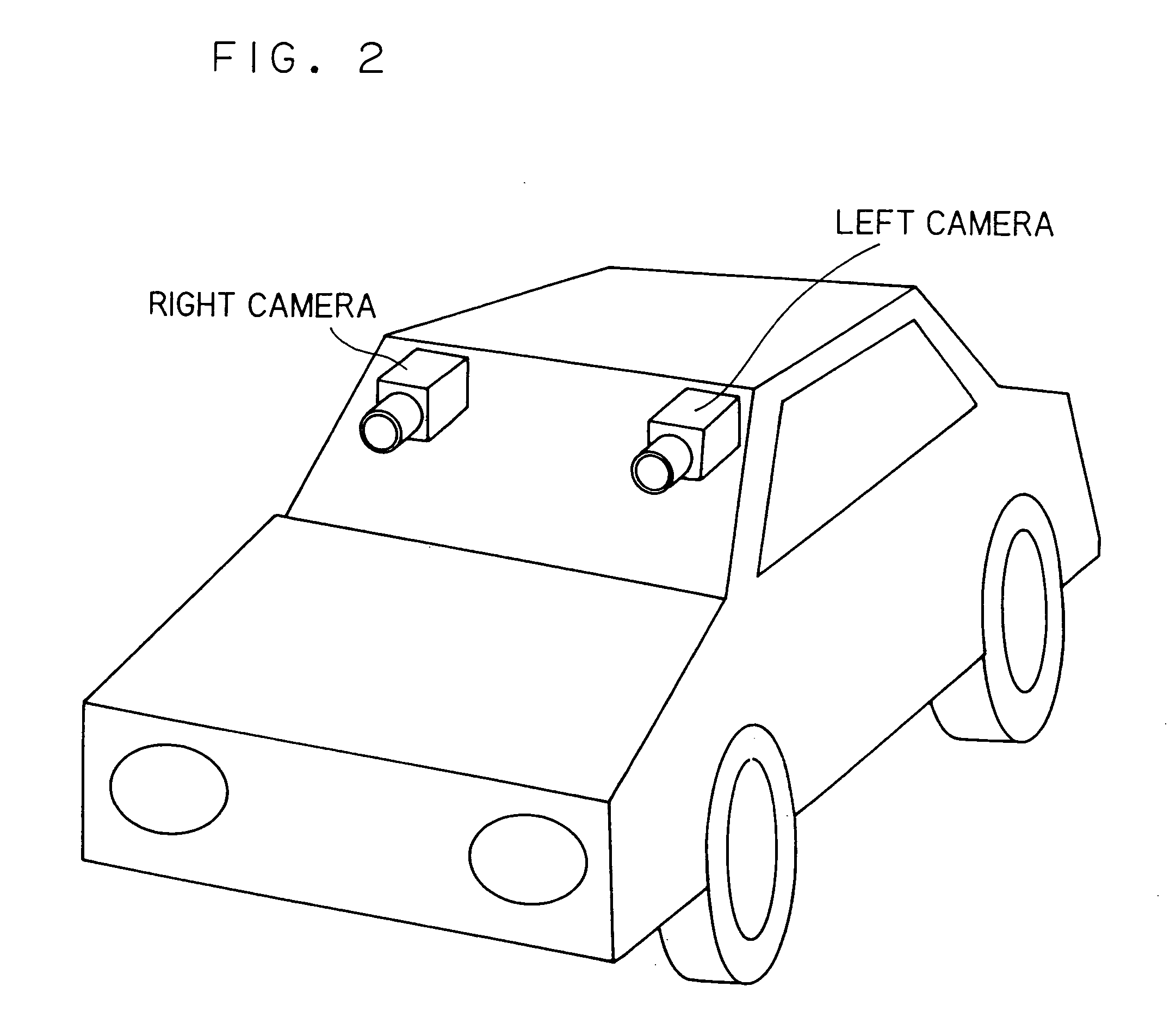
[0142] In the above, the detection regions R and R' are predetermined in the right and left camera images. Alternatively, such an obstacle detection method as described in Patent Literature 3 (JP-A-2001-154569) may be used for a preprocessing, and a result derived thereby may be used to set detection regions. To set detection regions, some driving lane detection method may be used, and a result derived thereby may be used under a predetermined method.

modification example 3

[0143] Even if no detection region is set in advance, the right and left camera images may be scanned, and at each scanning position, the operation of the embodiment may be executed for a similar object detection process.

modification example 4

[0144] In the present embodiment, the equation 10 and other between-image relational expressions and drawings are provided for conversion from the right image region to the left image region. Those are not surely restrictive, and all allow conversion from the left image to the right image.


PUM


Abstract

Provided is a technology for helping safe driving and realizing automatic driving of vehicles, or for counting the number of passing vehicles on the road or monitoring those passing vehicles for their driving. Using a plurality of cameras mounted in a vehicle or provided above a road, even if the relationship between the road plane and the respective cameras constantly changes in relative position or posture due to camera vibration or a change in road tilt, any obstacles located on the road such as other vehicles ahead, parked vehicles, and pedestrians on the road are detected without confusing those with textures including white lines, road signs, paint, road stains, and shadows of roadside objects, all of which do not disturb vehicle driving. An obstacle detection device 10 is structured by an image input section 11 for receiving images from a plurality of image pick-up devices 101, a correspondence detection section 12 for finding a plurality of pairs of corresponding points from the received right and left images, the slope degree calculation section 13 for calculating a slope degree of a plane including the corresponding points, and a result determination section 14 for determining as there being an obstacle when the calculated slope degree is larger than a predetermined value.

Description

[0001] This application is based upon and claims the benefit of priority from the prior Japanese Patent Application No.2002-249782, filed on 28 Aug. 2002; the entire contents of which are incorporated herein by reference.[0002] 1. Field of the Invention[0003] The present invention relates to an obstacle detection device for detecting any obstacles on a road without confusing those with textures using a plurality of cameras mounted in a vehicle or provided above the road, and a method applied to the device. Here, the obstacles are those located on the road such as other vehicles ahead, parked vehicles, and pedestrians. The textures include white lines, road signs, paint, road stains, and shadows of roadside objects, all of which do not disturb vehicle driving. The cameras are provided mainly for helping safe driving and realizing automatic driving of the vehicle, or for counting the number of passing vehicles on the road or monitoring those passing vehicles for their driving. Obstacl...

Claims


Application Information

Patent Timeline
Patent Type & Authority Applications(United States)
IPC IPC(8): B60R1/00B60R21/00G06K9/00G06T1/00G06T7/00G08G1/00G08G1/04G08G1/16H04N7/18
CPCG06K9/00651G06K9/00664G06K9/00798G06T7/004G06K9/00805G06T7/0075G06T2207/10021G06T2207/30261G08G1/16G06T7/0044G08G1/165G08G1/166G06T7/70G06T7/74G06T7/593G06V20/182G06V20/10G06V20/588G06V20/58
Inventor NAKAI, HIROAKIHATTORI, HIROSHITAKEDA, NOBUYUKIONOGUCHI, KAZUNORI
Owner KK TOSHIBA
Why Eureka
Try Eureka