Navigation system

a navigation system and positioning technology, applied in navigation instruments, maps/plans/charts, instruments, etc., can solve the problems of insatiable positioning correction using the on-board camera, difficult to obtain a high level of positioning accuracy using current positioning technology, and difficulty in ensuring 100% positioning accuracy. , to achieve the effect of high positioning accuracy

Active Publication Date: 2010-07-22
MITSUBISHI ELECTRIC CORP
View PDF16 Cites 31 Cited by
  • Summary
  • Abstract
  • Description
  • Claims
  • Application Information

AI Technical Summary

Benefits of technology

[0009]With the navigation system according to the present invention, a drift correction is performed on the angular velocity sensor in accordance with the angle error between the vehicle azimuth determined by the angular velocity sensor and the vehicle azimuth determined by recognizing an image from the on-board camera, and therefore correct angular velocity sensor information can be obtained from the angular velocity sensor at all times. As a result, a high level of positioning accuracy can be obtained.

Problems solved by technology

When complicated road conditions exist, as in Japan, it is particularly difficult to guarantee 100% positioning accuracy.
For example, in gaps between buildings, multistory parking lots, elevated roads and roads running underneath, multi-level interchanges, and so on, it may be still difficult to obtain a high level of positioning accuracy using current positioning technology.
As described above, although on-board cameras have substantially become standard equipment in recent navigation systems, positioning correction using the on-board camera is not yet satisfactory.

Method used


Image

  • Navigation system
  • Navigation system
  • Navigation system

Examples


embodiment 1

[0030]A navigation system in accordance with Embodiment 1 is assumed to be provided with a “rear camera” serving as an on-board or on-vehicle camera, and to operate upon installation in a vehicle.

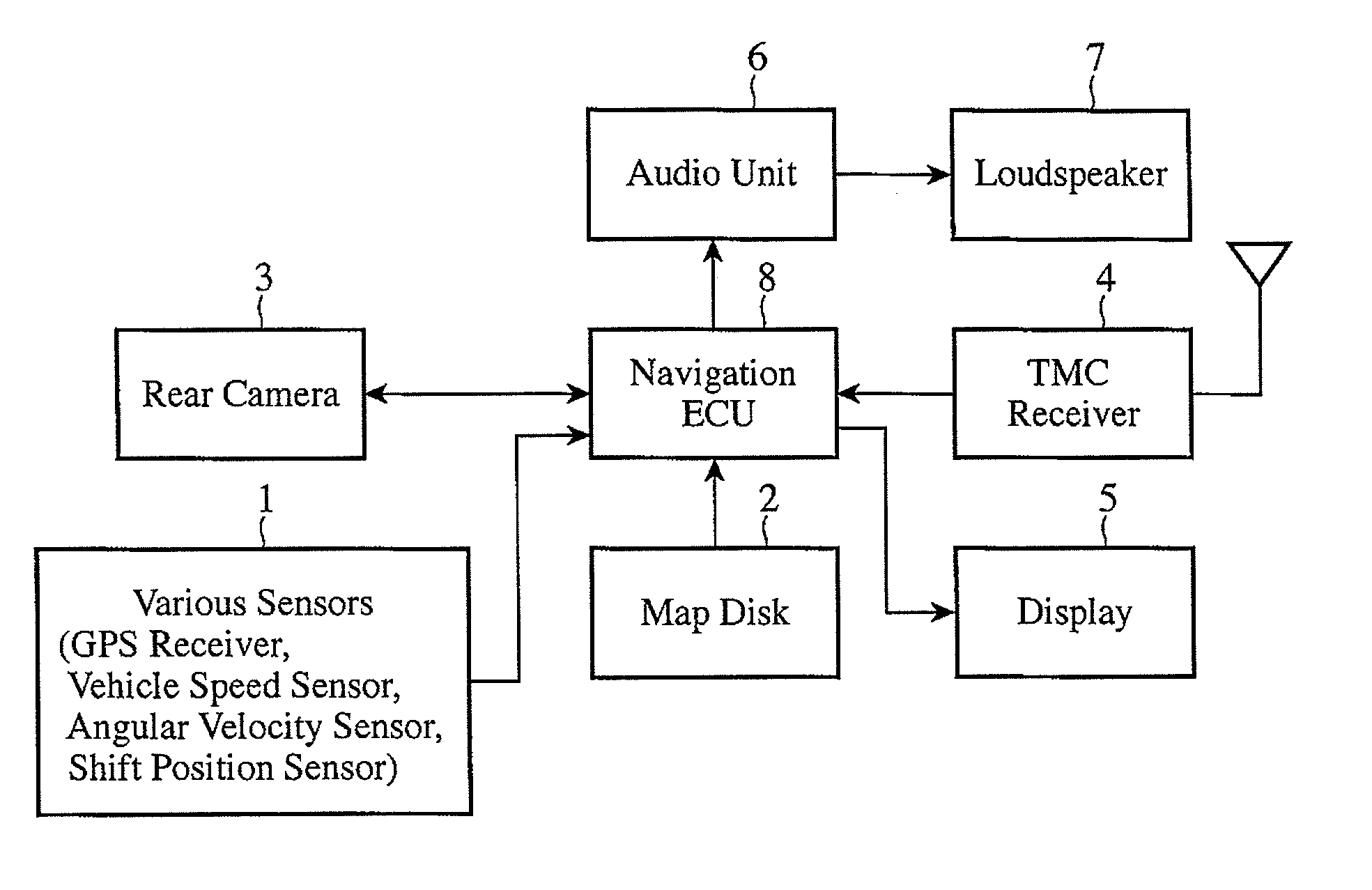
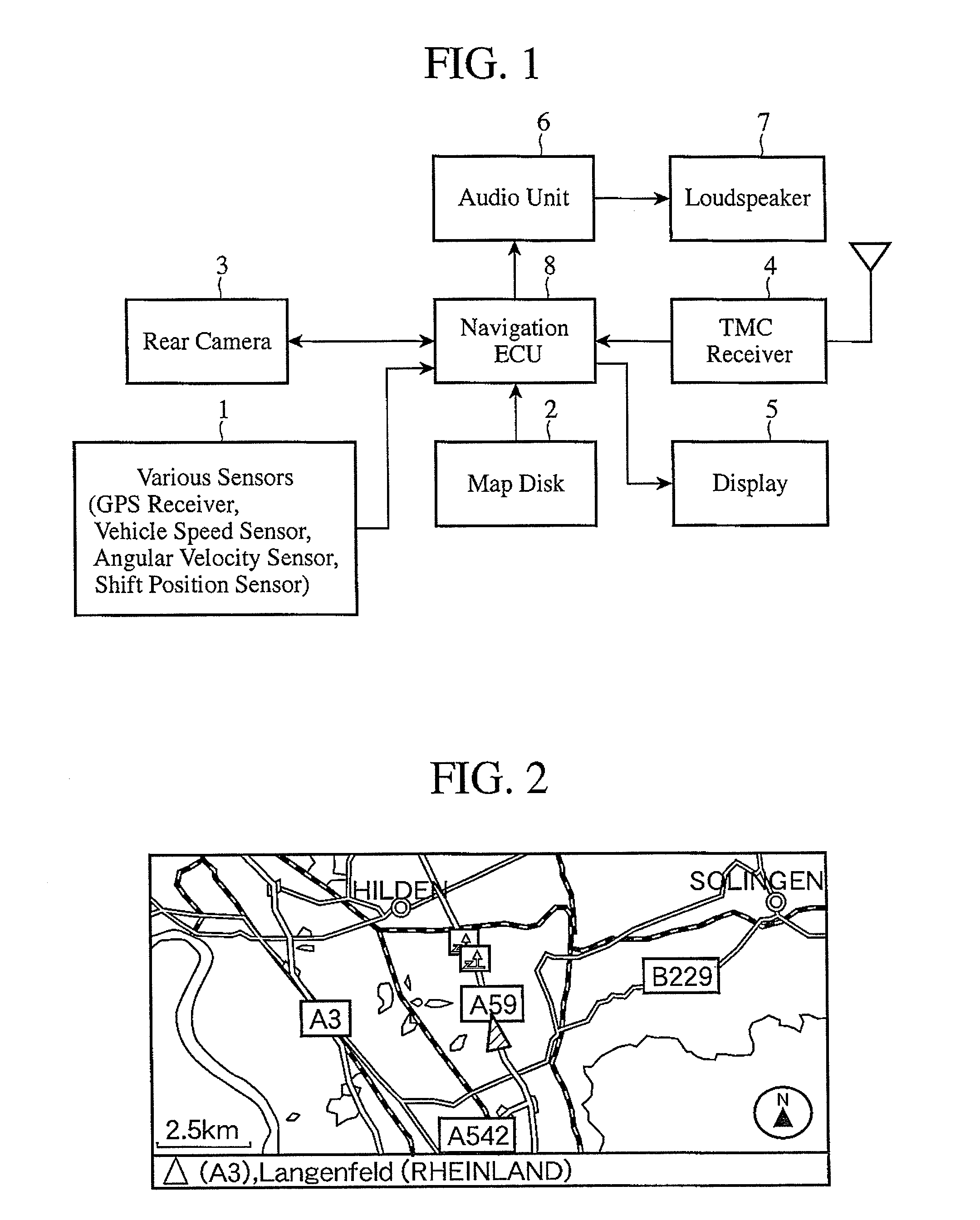
[0031]FIG. 1 is a block diagram showing the overall constitution of the navigation system in accordance with Embodiment 1 of the present invention. The navigation system includes various sensors 1, a map disk 2, a rear camera 3, a TMC (Traffic Message Channel) receiver 4, a display 5, an audio unit 6, a loudspeaker 7, and a navigation ECU (Electronic Control Unit) 8.

[0032]The various sensors 1 include a GPS receiver, a vehicle speed sensor, an angular velocity sensor, a shift position sensor, and so on. The GPS receiver receives GPS signals from GPS satellites constituting a global positioning system, and detects its own current position on the basis of the received GPS signals. The current position detected by the GPS receiver is transmitted to the navigation ECU 8 as GPS information.

[0033...


PUM


Abstract

A navigation system includes: an angular velocity sensor 1 for detecting a change in an advancement direction of a vehicle; a vehicle azimuth calculation unit 13 for calculating a vehicle azimuth on the basis of angular velocity sensor information obtained from the angular velocity sensor; an on-board camera 2 for shooting a periphery of the vehicle; an image recognition unit 19 for recognizing an image obtained from the on-board camera; and an offset voltage correction unit 21 for performing a drift correction on the angular velocity sensor in accordance with an angle error between the vehicle azimuth calculated by the vehicle azimuth calculation unit and a vehicle azimuth determined from a white line on a road recognized by the image recognition unit.

Description

TECHNICAL FIELD[0001]The present invention relates to a navigation system for guiding a user to a destination, and more specifically to a technique for improving positioning accuracy relating to a vehicle.BACKGROUND ART[0002]In recent years, vehicles including a rear view camera system that captures an image of the rear of the vehicle using a rear camera and displays the captured image have increased with the aim of ensuring safety during reversing the vehicle. Further, with increases in the number of buyers of luxury cars, on-board cameras including a rear camera are often provided as standard equipment in pre-installed navigation systems. Meanwhile, with advancements in image recognition technology, improvements have been made in image recognition precision.[0003]Under these circumstances, cost competition has escalated, and in a positioning technology that is an essential function of a navigation system, there is a demand for a technique with which a high level of positioning acc...

Claims


Application Information

Patent Timeline
Patent Type & Authority Applications(United States)
IPC IPC(8): G01C21/26
CPCG01C21/26G01C25/005G09B29/102
Inventor MONDE, YASUHIROHAYAMI, KATSUROFUJII, MASATOSHIMAEDA, ATSUSHI
Owner MITSUBISHI ELECTRIC CORP
Why Eureka
Try Eureka