Motorized locking mechanism

Active Publication Date: 2004-05-27
SARGENT MANUFACTURING CO INC
View PDF4 Cites 29 Cited by
  • Summary
  • Abstract
  • Description
  • Claims
  • Application Information

AI Technical Summary

Benefits of technology

[0019] A locking slide is driven by the connecting arm through a pivoting connection into and out of interfering engagement with the hub as the connecting arm is moved by the locking spring. The pivoting connection between the locking slide and the connecting arm has an axis of pivot that is parallel to the hub axis to protect the locking mechanism. The locking spring has sufficient spring action to allow the engaged portion of the spring to move to the first position even if the locking slide is prevented from moving to the locked position. The spring action of the locking spring is also sufficient to automatically relock the mechanism by moving the connecting arm to the locked position as soon as the locking slide is free to move.
[0023] The connecting arm is preferably L-shaped and includes a fork at an end thereof. The locking slide pivots within the fork. Another aspect of the preferred design is that the locking mechanism includes a housing and the connecting arm slides in guide slots formed in opposed inner surfaces of the housing. The housing supports all of the components of the locking mechanism, which allows the entire locking mechanism to be easily removed and replaced as a modular unit.
[0024] To prevent the locking spring from being damaged by work hardening and excessive bending, an end of the locking spring opposite the connecting arm is float mounted, preferably between a pair of opposed compression springs.

Problems solved by technology

A particular problem with motorized locking mechanisms relates to the forces that can be applied from the hub to the locking mechanism through the locking slide.
This high level of torque can apply a damaging level of force to the internal components of the locking mechanism through the locking slide.
However, the locking slide may cock or move slightly in undesired ways, particularly under high load levels when the lock mechanism is worn.
This undesired motion can drive the motor or other parts of the locking mechanism in undesired and potentially damaging directions and / or apply a damaging level of force to the motorized system for moving the locking slide.
Another problem with motorized designs of this type is that the locking slide may be temporarily prevented from moving to or from the locked position.
Although inconvenient, a user can simply operate the lock again if he has prevented the door from unlocking by prematurely applying a rotational force to the handle.
However, if the user has prevented the mechanism from relocking, by keeping the handle rotated beyond the access period, the door will remain unlocked if the motorized lock is incapable of relocking automatically after the handle is released.
This method is relatively expensive to implement due to the cost of the sensors and additional electronics required.
A related difficulty is that the motor system must be properly designed so that it does not damage itself or any other part of the lock if the motor is energized while the locking slide is prevented from moving.
The use of a spring for automatic relock of a motor-driven, vertically moving, locking slide has been problematical.

Method used


Image

  • Motorized locking mechanism
  • Motorized locking mechanism
  • Motorized locking mechanism

Examples


Embodiment Construction

)

[0032] In describing the preferred embodiment of the present invention, reference will be made herein to FIGS. 1-4 of the drawings in which like numerals refer to like features of the invention.

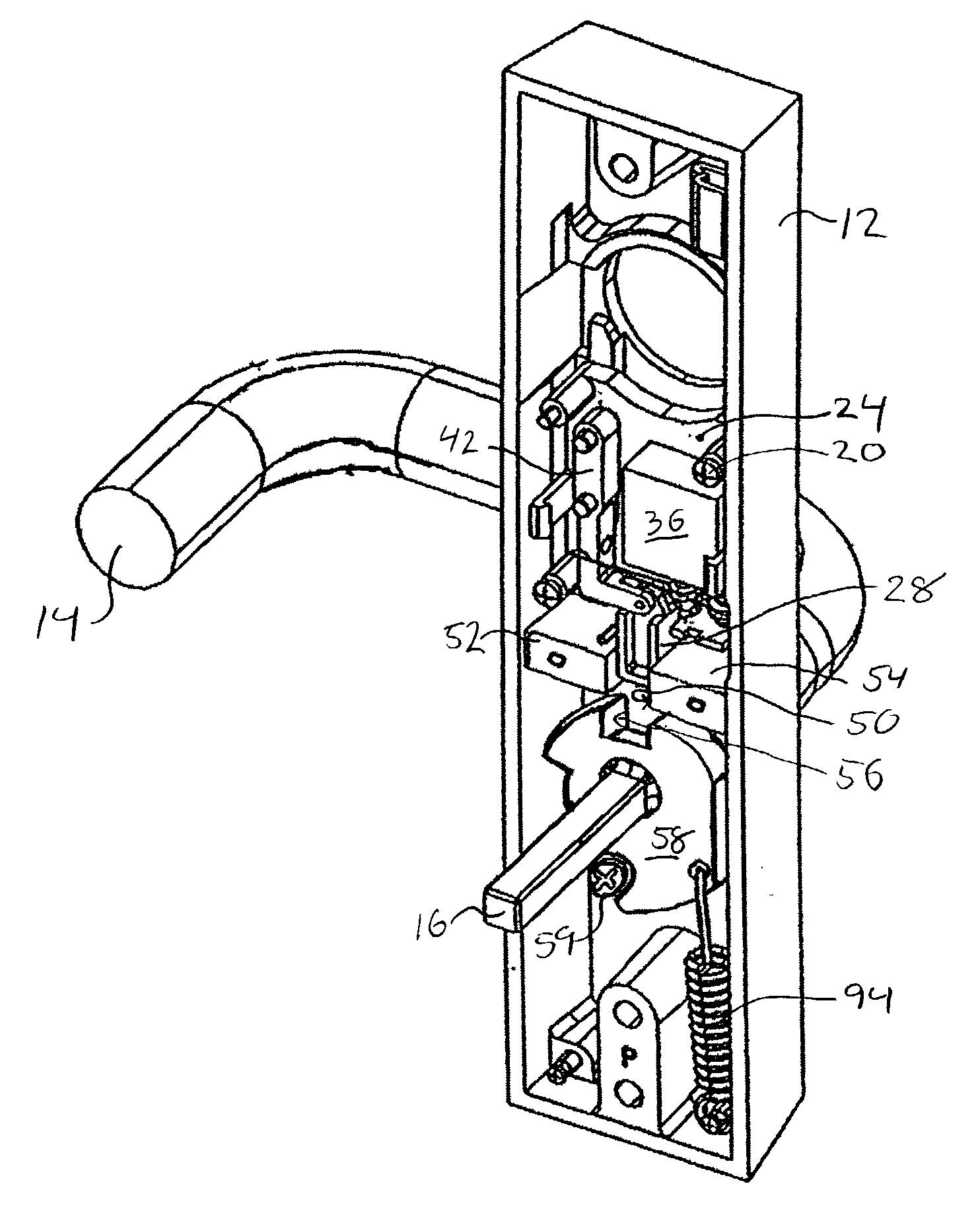
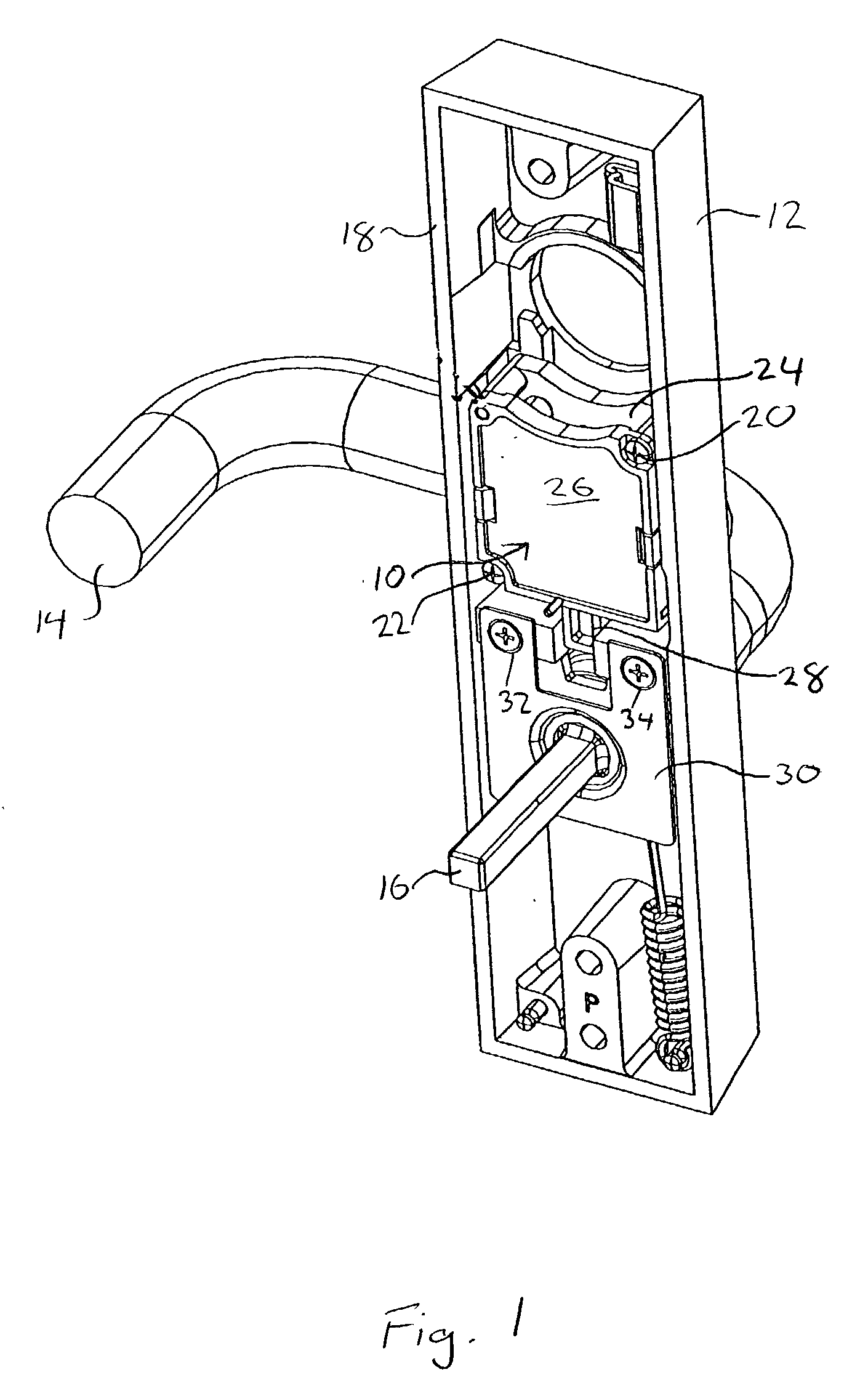
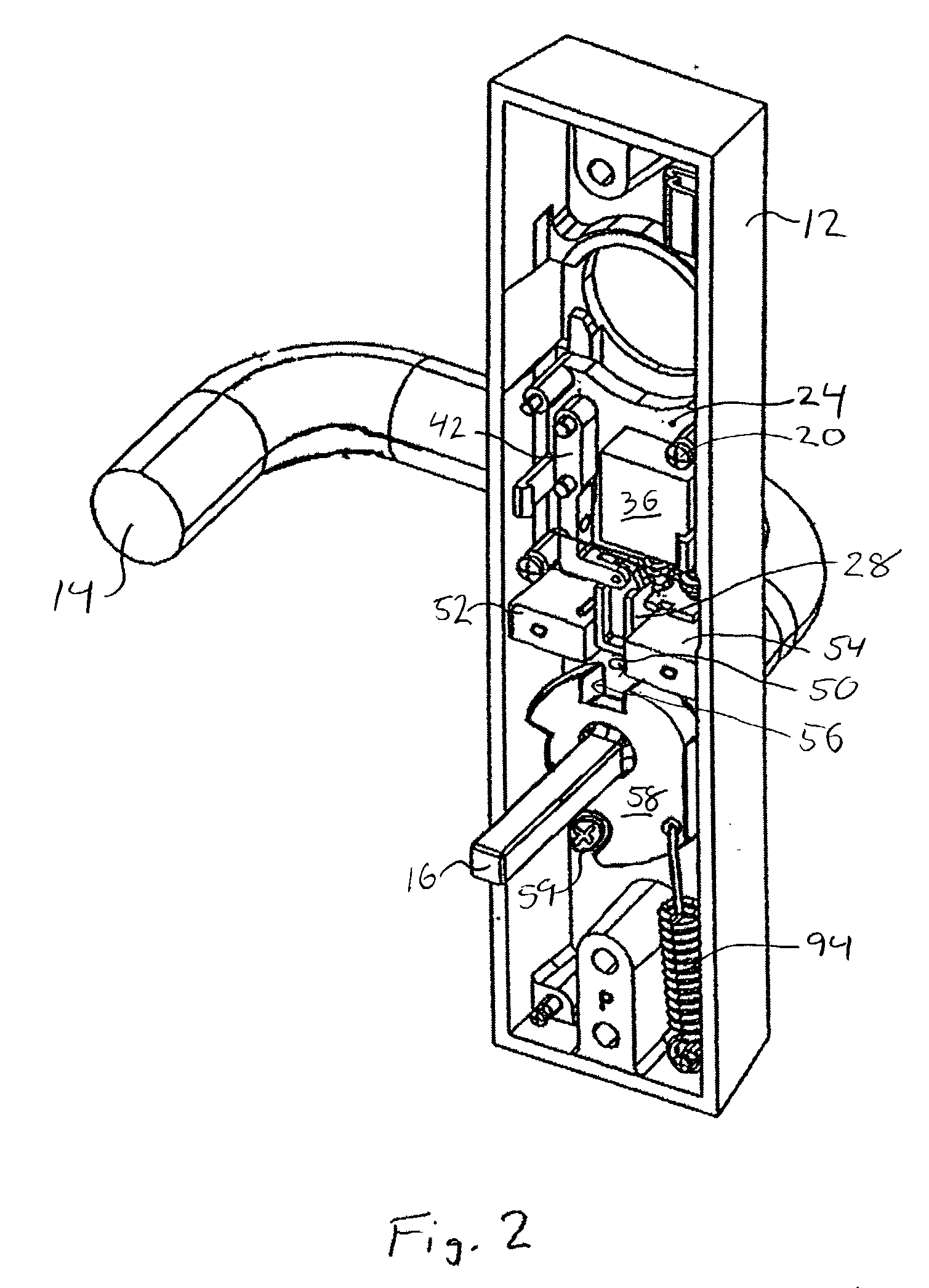
[0033] Referring to FIG. 1, a motorized locking mechanism 10 according to the present invention is installed within an exit trim housing 12. The exit trim includes a lever handle 14 that rotates a spindle 16 to operate an exit device. The exit trim is installed on the outer side of the exit door with perimeter edge surface 18 flush against the door. The spindle 16 extends through the exit door and into a conventional exit device (not shown) installed directly opposite the trim housing 12 on the inner side of the exit door.

[0034] All of the components of the locking mechanism 10 are ultimately mounted to or supported by a frame 24 and its removable front cover 26. The complete locking mechanism can be removed as a modular unit from the housing 12 and replaced by removing two mounting screws 2...


PUM


Abstract

A motorized locking mechanism for locking and unlocking a device having a hub rotatable by a handle about a hub axis. A reversible motor turns a threaded spring screw to move a locking spring and vertically drive a connecting arm between locked and unlocked positions. A locking slide is mounted on an end of the connecting arm so that it can pivot parallel to the hub axis. As the motor drives the connecting arm to the locked position, the locking slide moves into interfering engagement with the hub to lock the device. The pivoting motion of the locking slide protects the locking mechanism, and particularly the connecting arm, against damaging forces that can be applied by the rotating hub through the locking slide. If the locking slide is temporarily prevented from moving into or out of locking engagement with the hub, the motor may still turn and the locking spring subsequently moves the locking slide in the desired direction without the necessity of reactivating the motor. The locking spring characteristics and mounting, and the pitch of the spring screw threads, are selected so that the connecting arm and locking slide may be lifted and continuously supported vertically.

Description

[0001] 1. Field of the Invention[0002] The present invention relates to locking mechanisms for doors that are locked and unlocked electrically.[0003] 2. Description of Related Art[0004] Motorized locking mechanisms are used in applications that require a lock to be operated electrically. Although there are many such applications, one illustrative use is in the outside handle trim for an exit device operated by a keypad. Outside trim of this type is installed on the exterior side of an exit door of a commercial building where the exit door will also be used by authorized personnel to enter the building. The trim piece includes a handle having a spindle that turns a hub. The spindle extends through the exit door and into the exit device mounted on the inner side of the door.[0005] Motorized locks used in this application typically have a motor that drives a locking slide into and out of locking engagement with a hub on a spindle attached to the handle. Turning the handle rotates the h...

Claims


Application Information

Patent Timeline
IPC IPC(8): E05B47/00E05B47/06
CPCE05B17/0058E05B47/0012E05B47/0673E05C19/06E05B2047/0031E05B2047/0036E05B2047/0016Y10T70/713Y10T70/55Y10T70/7051Y10T70/7102E05B47/06
Inventor NUNEZ, PAUL
Owner SARGENT MANUFACTURING CO INC
Why Eureka
Try Eureka