
Multilevel Fabricators

Active Publication Date: 2016-05-12
FLITSCH FREDERICK A
View PDF0 Cites 2 Cited by
  • Summary
  • Abstract
  • Description
  • Claims
  • Application Information

AI Technical Summary

Benefits of technology

This patent discusses the use of a cleanspace fabricator in a manufacturing environment. The fabricator uses processing tools that are oriented vertically and placed in a peripheral location relative to where workproduct is moved. The tools are easily removable and replaceable, which can be automated. The process tools and automation can be redesigned and installed into the cleanspace fabricator. This allows for efficient production of various types of production units, including biomedical devices, semiconductor devices, and testing systems, among others. The use of a cleanspace fabricator and its design features also allows for effective removal of contamination sources and particulate from the production environment.

Problems solved by technology

However, known cleanroom design has disadvantages and limitations.
For example, as the size of tools has increased and the dimensions of cleanrooms have increased, the volume of cleanspace that is controlled has concomitantly increased.
As a result, the cost of building the cleanspace, and the cost of maintaining the cleanliness of such cleanspace, has increased considerably.
Tool installation in a cleanroom can be difficult.
However, as tools are put in place and a fabricator begins to process substrates, it can become increasingly difficult and disruptive of job flow, to either place new tools or remove old ones.
Likewise it has been difficult to remove a sub-assembly or component that makes up a fabricator tool in order to perform maintenance or replace such a subassembly or component of the fabricator tool.

Method used


Image

  • Multilevel Fabricators
  • Multilevel Fabricators
  • Multilevel Fabricators

Examples


Embodiment Construction

[0033]As manufacturing lines age and as product lifecycles progress, it is possible for a cleanliness requirement for products to evolve and to require changes in the inherent aspects of production. In some cases, the changes require new replacement tooling or improved materials aspects, while in others the environment that tooling resides in needs to be upgraded. Whether the current environment is a cleanroom type of environment or not, an effect means of retrofitting the environment may be to retrofit the existing manufacturing line into a cleanspace based fabricator manufacturing line.

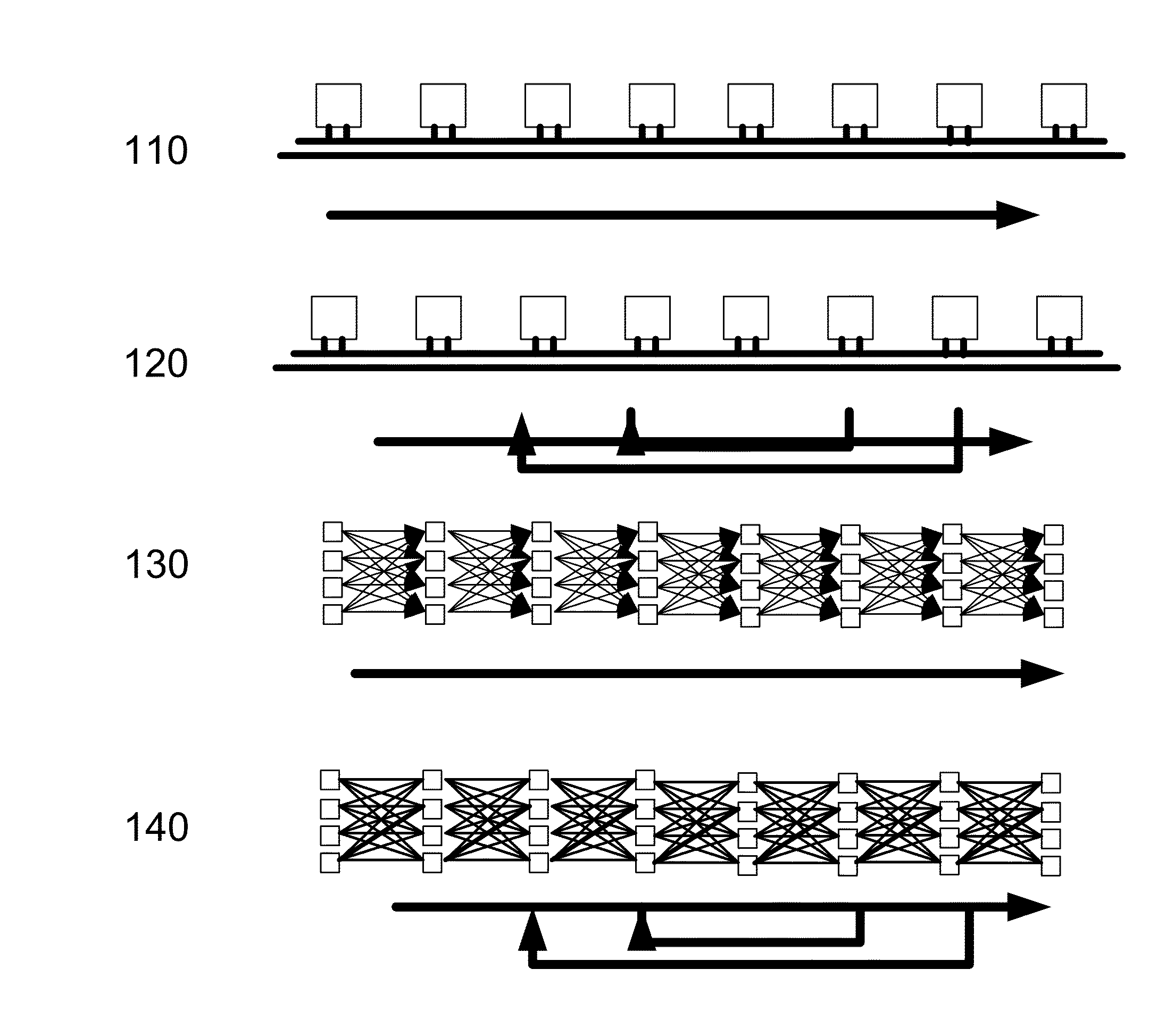
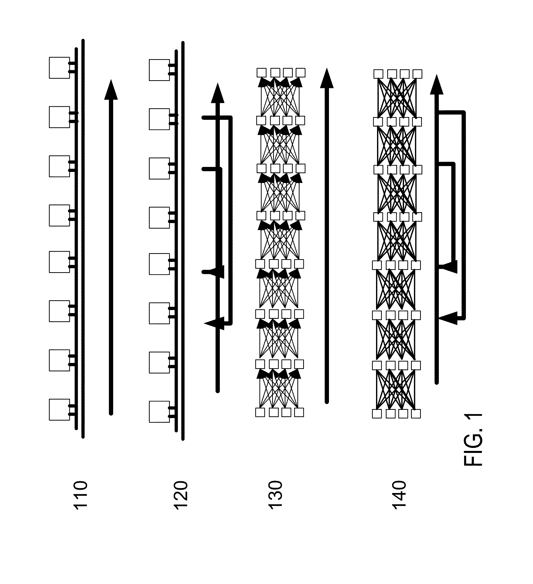
[0034]Proceeding to FIG. 1, item 110 demonstrates an exemplary case for manufacturing where the processing tools are located in a serial fashion. A work product is moved from one tool to the next tool after a process is complete and then by moving the work product to the end of the processing tools a complete product is obtained.

[0035]A somewhat different condition is demonstrated by item 120, where...


PUM


Abstract

The present invention provides various aspects for supporting multilevel fabricators. In some examples, the multilevel fabricators may include a cleanspace region for moving work material. In some examples, panels of filters may be positioned to support the cleanspace. In some embodiments existing processing equipment and automation are placed into the new environment. In other embodiments the processing equipment is placed and new automation equipment is used. Automated tool placement equipment may be used to place the equipment. In some examples, automated tool handling equipment may be used to remove and replace processing equipment into the multilevel fabricator.

Description

CROSS REFERENCE TO RELATED APPLICATIONS[0001]This application claims priority to the U.S. patent application Ser. No. 13 / 747,091 filed Jan. 22, 2013 as a continuation in part. This application claims priority to the U.S. patent application Ser. No. 14 / 703,552 filed May 4, 2015 as a continuation in part; which in turn claims priority to the U.S. patent application Ser. No. 14 / 134,705 filed Dec. 19, 2013 now U.S. Pat. No. 9,159,592 issued Oct. 13, 2015; which in turn claims the benefit of the U.S. Provisional Application 61 / 745,996 filed Dec. 26, 2012. This application is a continuation in part of the Utility application, Ser. No. 14,689,980, filed Apr. 17, 2015 and entitled: “Method and Apparatus for Vertically Orienting Substrate Processing Tools in a Cleanspace.” The application Ser. No. 14 / 689,980 in turn is a continuation in part of the Utility application, Ser. No. 13 / 398,371, filed Feb. 16, 2012 now U.S. Pat. No. 9,059,227, issued Jun. 16, 2015 and entitled: “Method and Apparat...

Claims


Application Information

Patent Timeline
IPC IPC(8): G05B19/418
CPCG05B19/4189G05B2219/45031G05B2219/31276H01L21/67017H01L21/67178H01L21/67733H01L21/67736
Inventor FLITSCH, FREDERICK A.
Owner FLITSCH FREDERICK A
Learn More