Heat sink for optical module array assembly

Active Publication Date: 2015-11-12
PROPHOTONIX IRL LTD
View PDF2 Cites 3 Cited by
  • Summary
  • Abstract
  • Description
  • Claims
  • Application Information

AI Technical Summary

Benefits of technology

The present invention is a new heat sink for an optical module array assembly that allows for easy removal and replacement of defective optical modules without special tools in a short period of time. It is suitable for different sizes of optical module array assemblies and includes features to ensure proper orientation of the optical modules relative to the PCB for correct electrical connection.

Problems solved by technology

However, as the optical power of the light source increases, the amount of heat generated by the light source also increases, and dissipating this heat can present significant technical challenges to the designer, particularly where the optical module is used in an optical module array assembly where a sizable number of optical modules must be packaged in a relatively confined space.
However, not all optical modules have monitor photodiodes incorporated therein, so the risk of the light source overheating and failing without appropriate detection is substantial.
This “excessive heat” issue is further compounded by the continuous release of new light sources with higher output powers from light source manufacturers, and the placement of high power optical modules in close proximity to each other so as to form dense arrays in optical module array assemblies.
However, optical modules installed in a heat sink have traditionally been difficult to remove and replace.
As old optical modules become defective, replacement optical modules can simply be plugged into the existing PCB, leading to significant cost savings.
Failure to do so results in malfunction of the laser diode and permanent damage to the laser diode when a voltage is applied.

Method used


Image

  • Heat sink for optical module array assembly
  • Heat sink for optical module array assembly
  • Heat sink for optical module array assembly

Examples


second embodiment

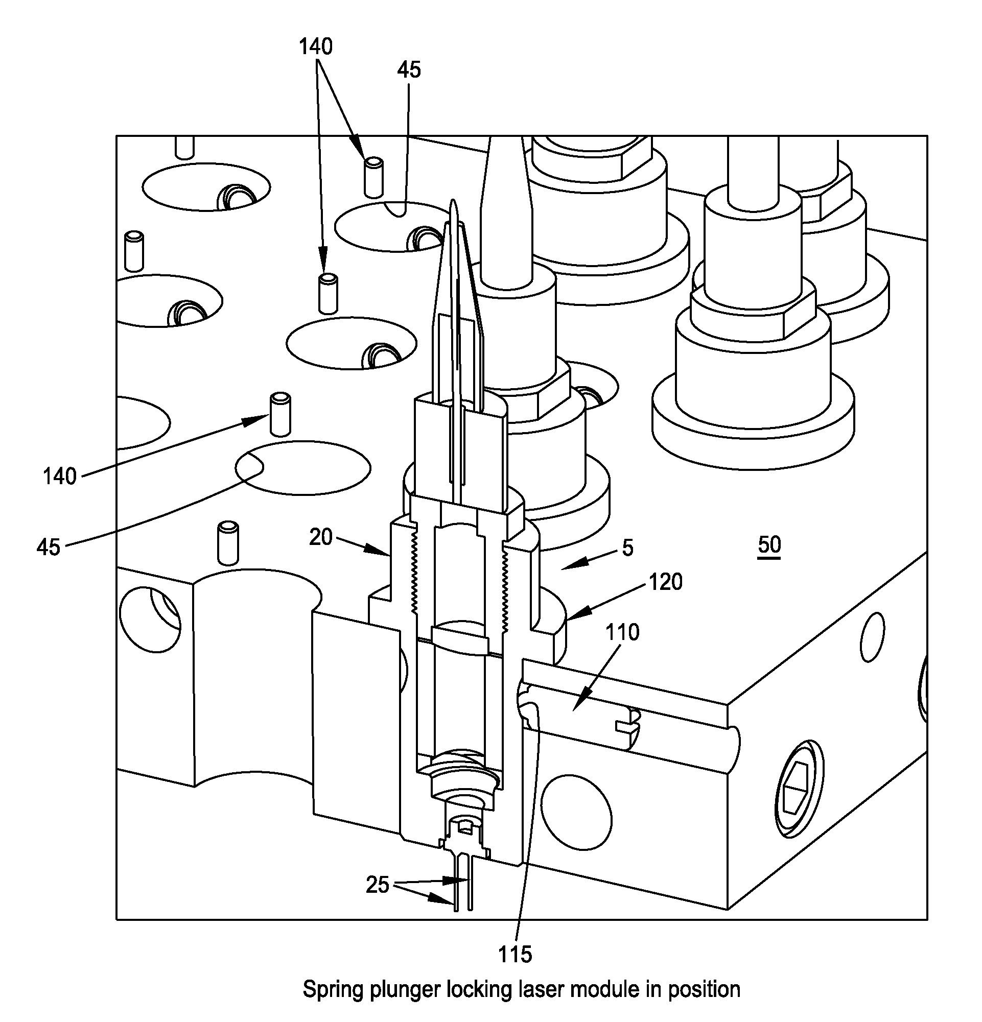
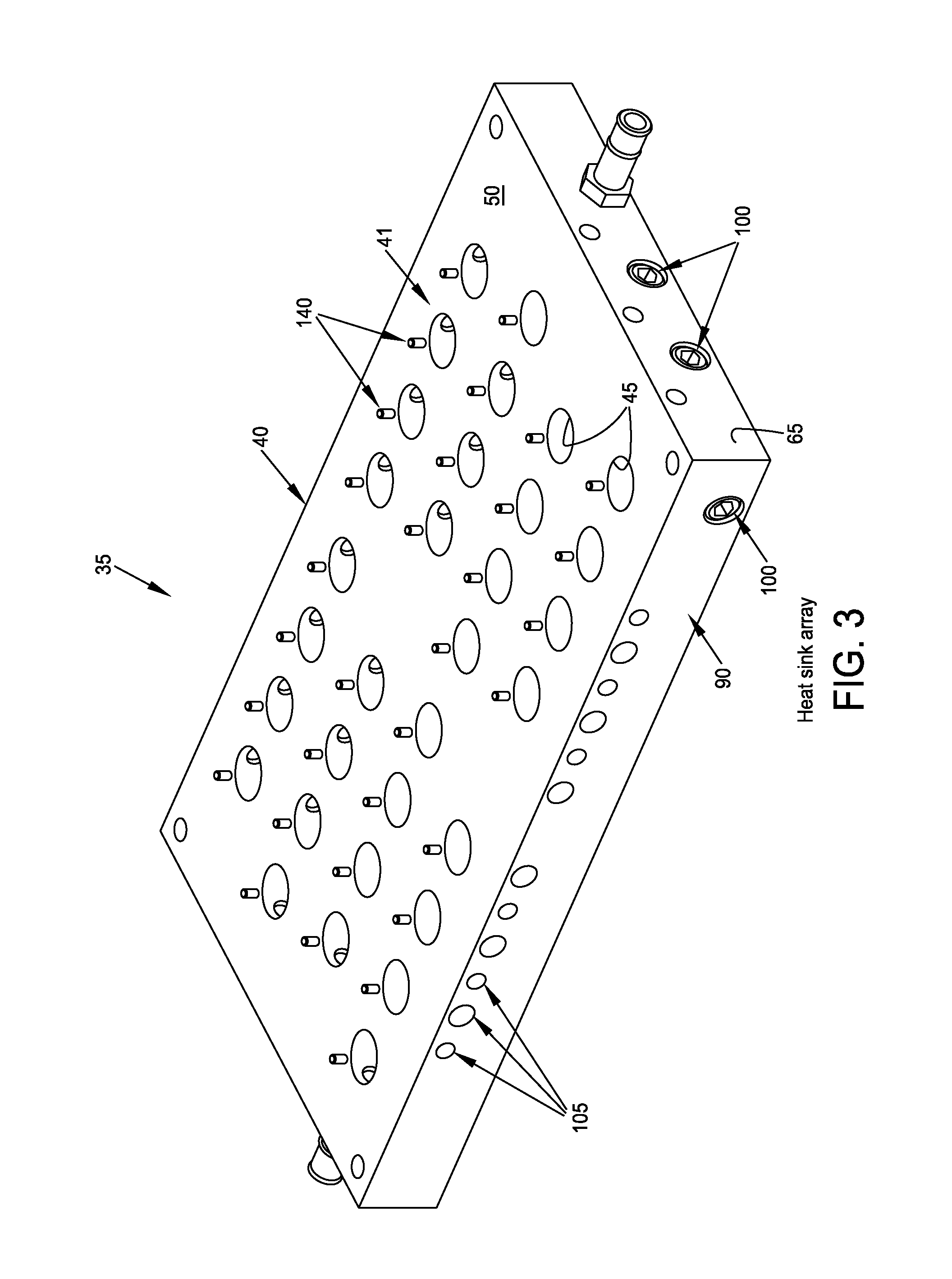
[0063]In the constructions shown in FIGS. 3-9, body 40 of heat sink 35 is shown as being formed by a single plate 41. However, and looking now at FIGS. 10 and 11, body 40 of heat sink 35 can also be formed using two plates 41A, 41B instead of one plate 41. In this form of the invention, the spring plungers 110 for holding the optical modules 5 tightly in the heat sink 35 are preferably located in the bottom plate 41B. The registration pins 140 are located in top plate 41A. The serpentine channel 75, through which the cooling fluid travels, may be drilled out in both plates, e.g., the lower half of serpentine channel 75 may be formed in bottom plate 41B and the upper half of serpentine channel 75 is formed in top plate 41A. To ensure that the cooling fluid does not leak out of heat sink 35, individual O-rings 145 (FIG. 11) may be located around the openings 45 in the heat sink plates 41A, 41B. A further primary O-ring 150 (FIG. 10) may be located around the peripheries of the two pla...

third embodiment

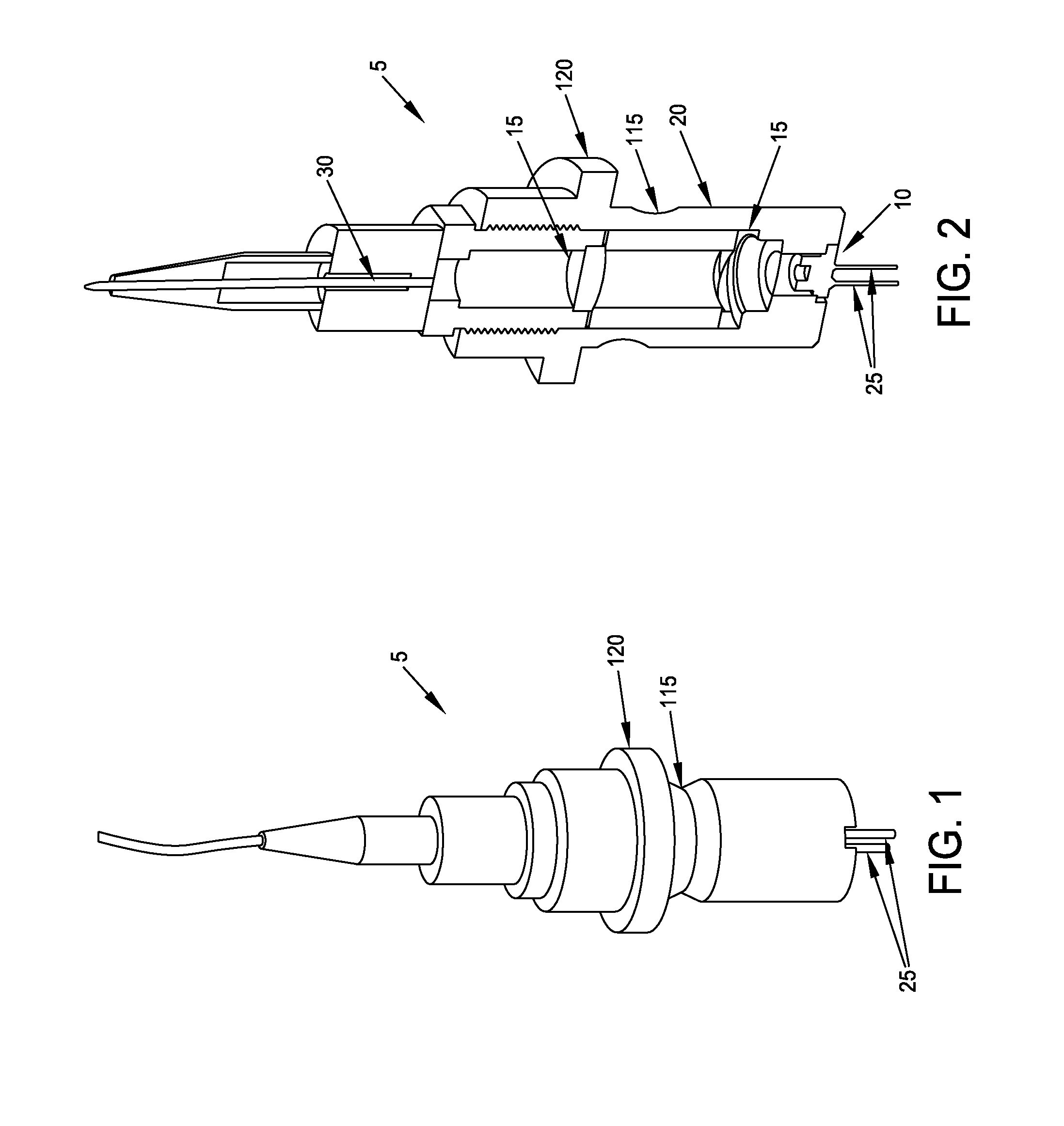
[0064]Heat sink 35 can be manufactured such that optical modules 5 are held in place by a screw (e.g., a set screw) rather than by spring plungers 110.

[0065]Alternatively, optical modules 5 may be held in place by screwing a screw directly through the lip 120 of every optical module 5 into the body 40 of heat sink 35. If desired, more than one screw can be used to secure each module 5 to body 40 of heat sink 35.


PUM


Abstract

Apparatus comprising: a heat sink, the heat sink comprising: a body formed out of a heat-transmissive material; at least one channel extending through the body, the at least one channel having an inlet port and an outlet port; at least one opening extending through the body, the at least one opening being configured to receive an optical module therein; at least one securement element mounted to the body for releasably securing an optical module within the at least one opening; and at least one alignment element mounted to the body for ensuring appropriate alignment of an optical module received in the at least one opening.

Description

REFERENCE TO PENDING PRIOR PATENT APPLICATION[0001]This patent application claims benefit of pending prior U.S. Provisional Patent Application Ser. No. 61 / 989,269, filed May 6, 2014 by ProPhotonix Limited and Adrian Zagoneanu for HEAT SINK FOR OPTICAL MODULE ARRAYS (Attorney's Docket No. PROPHOTONIX-1 PROV), which patent application is hereby incorporated herein by reference.FIELD OF THE INVENTION[0002]This invention relates to optical modules and optical module array assemblies in general, and more particularly to heat sinks for optical modules and optical modules array assemblies.BACKGROUND OF THE INVENTION[0003]There has been increasing demand for optical modules with higher optical output to use as light sources or for processing applications.[0004]The operating lifetime of a light source (e.g., a laser diode) is dependent on, among other things, its operating temperature. A high quality light source, operating at 20° C., could have a lifetime in excess of 100,000 hours. However...

Claims


Application Information

Patent Timeline
IPC IPC(8): G02B6/42
CPCG02B6/426G02B6/4269G02B6/4204G02B6/4249G02B6/428
Inventor ZAGONEANU, ADRIAN
Owner PROPHOTONIX IRL LTD
Why Eureka
Try Eureka