Bond test systems with offset shear tool

a test system and shear tool technology, applied in the field of shear tools, can solve the problems of inability to dynamically view the shear test set-up, inability to automatically index and accurately align the test tool with real-time feedback, and difficulty in operators' viewing of the test set-up for alignment through microscope eyepieces

Inactive Publication Date: 2004-06-03
COX MALCOLM
View PDF4 Cites 21 Cited by
  • Summary
  • Abstract
  • Description
  • Claims
  • Application Information

AI Technical Summary

Problems solved by technology

a) Current shear tool, test transducer and microscope arrangements do not allow direct viewing of the shear test and forces the microscopes required to set-up tests to be placed in an ergonomically compromised position.
b) The targeting of the ball to be tested is not in real time, the operator does not have a normal view of the shear tool relative to the bond to be tested and must therefore infer its position from a partial front angle view.
c) The requirement to view...

Method used


Image

  • Bond test systems with offset shear tool
  • Bond test systems with offset shear tool
  • Bond test systems with offset shear tool

Examples


Embodiment Construction

[0047] The preferred embodiment of the invention follows.

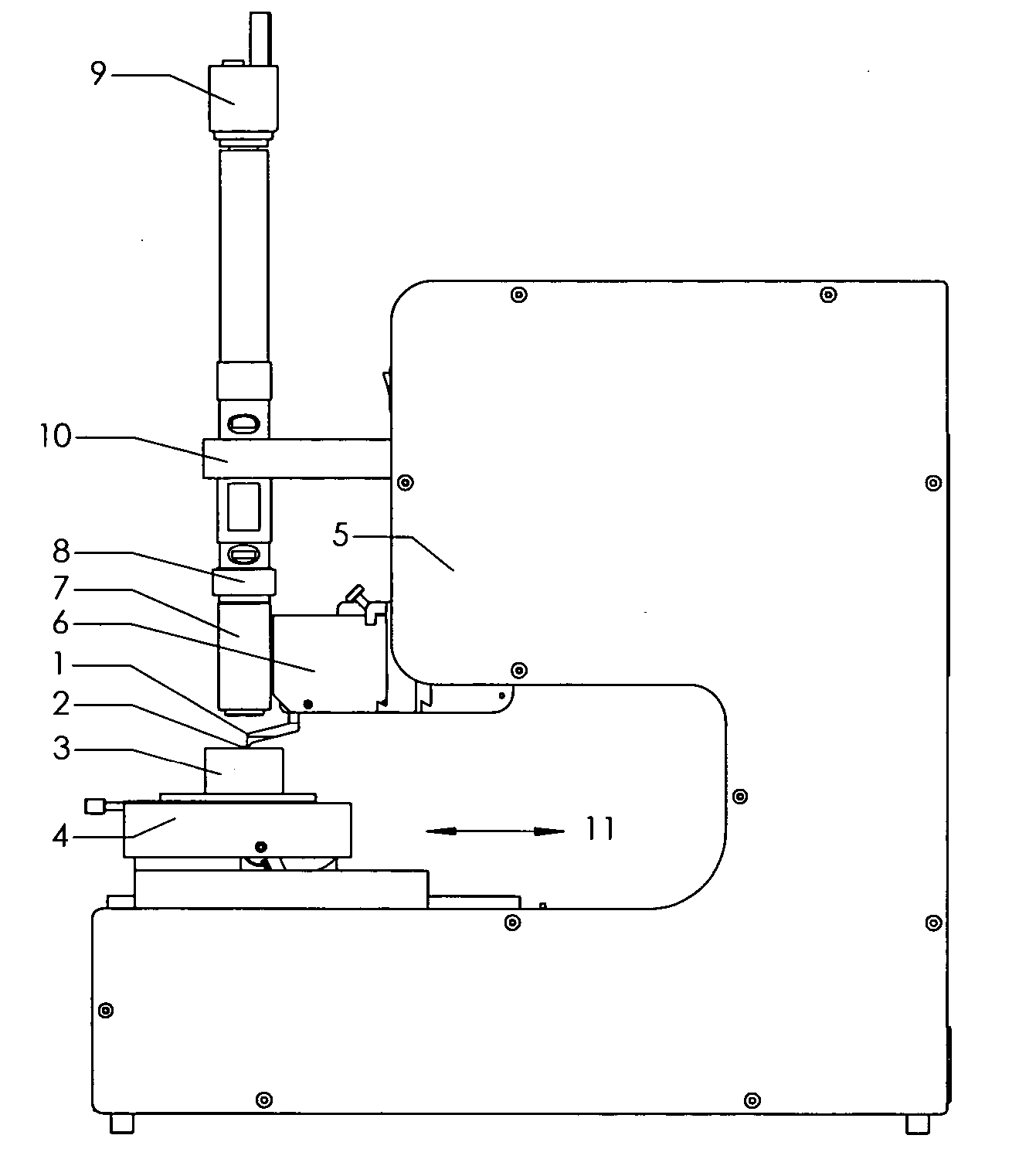
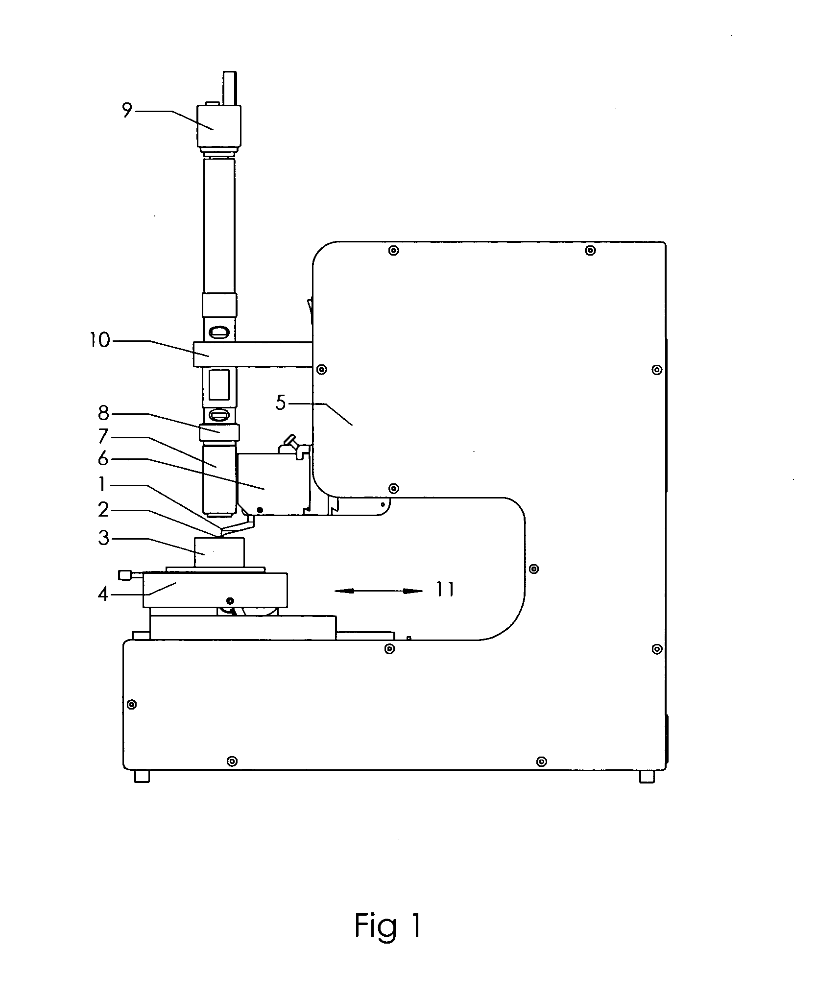
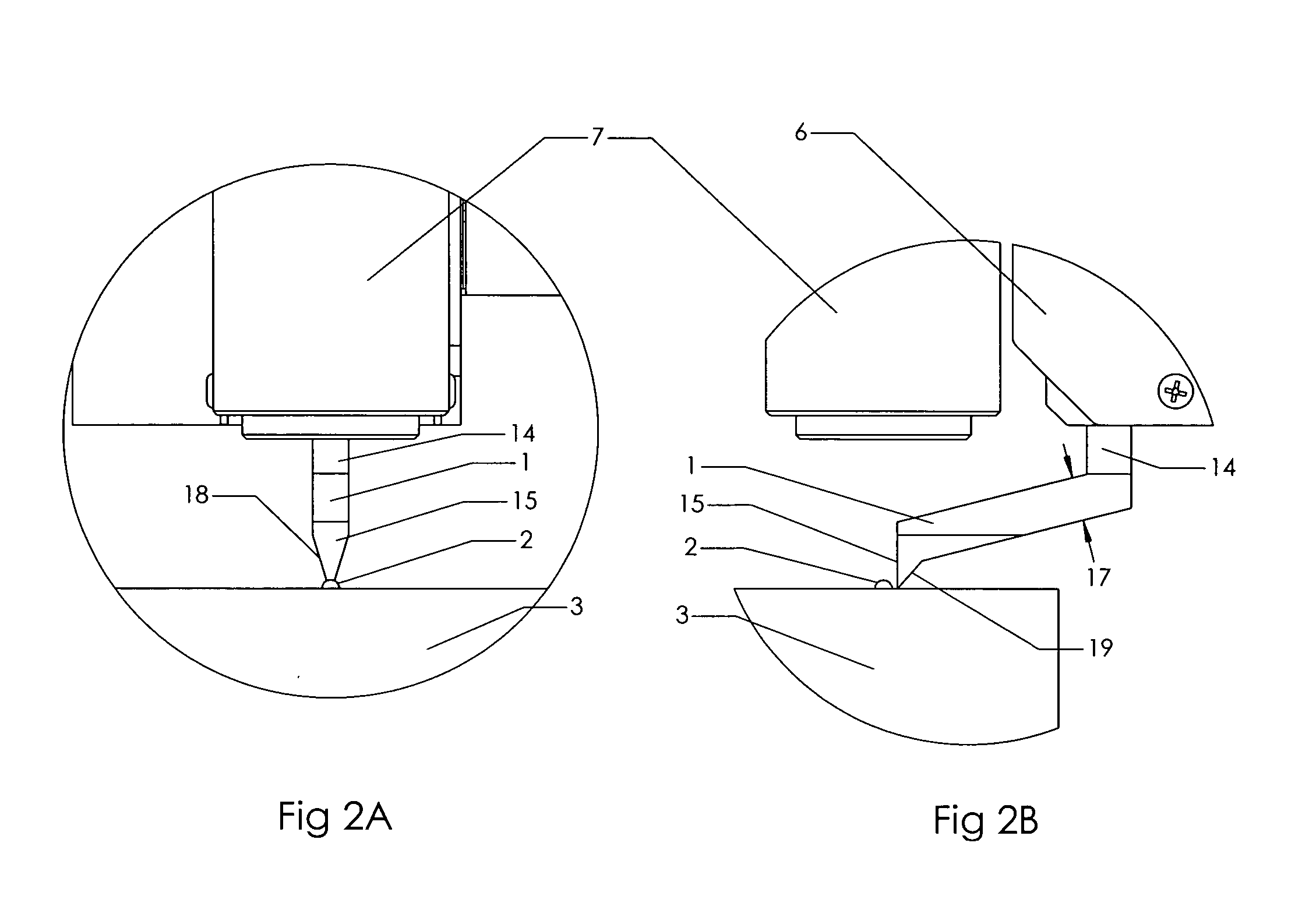
[0048] a) The special shear tool 1 features an offset 16 design that transfers the shear test force from a test area that can be viewed from a normal direction to the load axis of the force measurement transducer of the test module 6.

[0049] b) The tool features a blade edge on the shear face of the tool 15 that contacts the ball or bump to be tested, to contact only one ball or bump 2 per test, sized to be least as wide as the ball diameter with additional width for alignment tolerance, but no wider than the pitch distance between balls. Typical width is 1.5.times.ball diameter.

[0050] c) A keyed shank 14 with a flat 13 that allows fitment into the receiver socket of the force measurement transducer of the test module 6 in the correct position and orientation.

[0051] d) A section size 17 suitable to transfer the forces of the shear test from the shear face 15 to the shank 14.

[0052] e) Clearance angles from shear face 15 to shank...


PUM


Abstract

A tool 1 to be installed into a test module 6 of a Bond Test System 5 to provide the capability to directly view a bond shear test. This capability enables a vision system camera 9 coupled to magnifying optics 8 to provide real time viewing, image capture, and vision guided automation for more effective analysis, additional analytic capability and improved ergonomics. This greatly enhances the utility of the shear test function of the Bond Test System 5.

Description

CROSS-REFEENCE TO RELATED APPLICATIONS[0001] Not applicable[0002] 1. Field of Invention[0003] This invention relates to a novel and unique shear tool utilized in conjunction with a Bond Test System employed in the manufacture of microelectronics devices, for the expressed purpose of allowing a CCD camera based electronic vision system to have an unobstructed normal view of the shear test, thus enabling real time targeting, image capturing and remote viewing of bond tests and automated testing.[0004] 2. Description of Prior Art[0005] Various structures of microelectronic devices employ bonding techniques as part of the assembly of the devices, most notably, but not limited to, wire lead connections that interconnect integrated circuit chips to external lead frames, ball or bump bonds, or die bonds. Highly accurate test systems exemplified by Royce Instruments Inc model 552 and 580 Bond Testers have been developed to measure the strength of these bonds as a means of process control, d...

Claims


Application Information

Patent Timeline
IPC IPC(8): G01N3/00G01N3/24
CPCG01N3/24G01N2203/0067G01N2203/0025
Inventor COX, MALCOLM
Owner COX MALCOLM
Why Eureka
Try Eureka