Variable impedance matching circuit

a matching circuit and impedance technology, applied in the field of impedance matching circuits, can solve the problems that the matching method using the stub and the lumped elements of the prior art cannot vary the matching circui

Inactive Publication Date: 2004-06-03
ELECTRONICS & TELECOMM RES INST
View PDF1 Cites 39 Cited by
  • Summary
  • Abstract
  • Description
  • Claims
  • Application Information

AI Technical Summary

Problems solved by technology

Therefore, the matching methods using the stub and the lumped elements of the prior art can not vary the matching circuit after the matching circuit has been implemented as a hybrid or an integrated circuit.

Method used


Image

  • Variable impedance matching circuit
  • Variable impedance matching circuit
  • Variable impedance matching circuit

Examples


Embodiment Construction

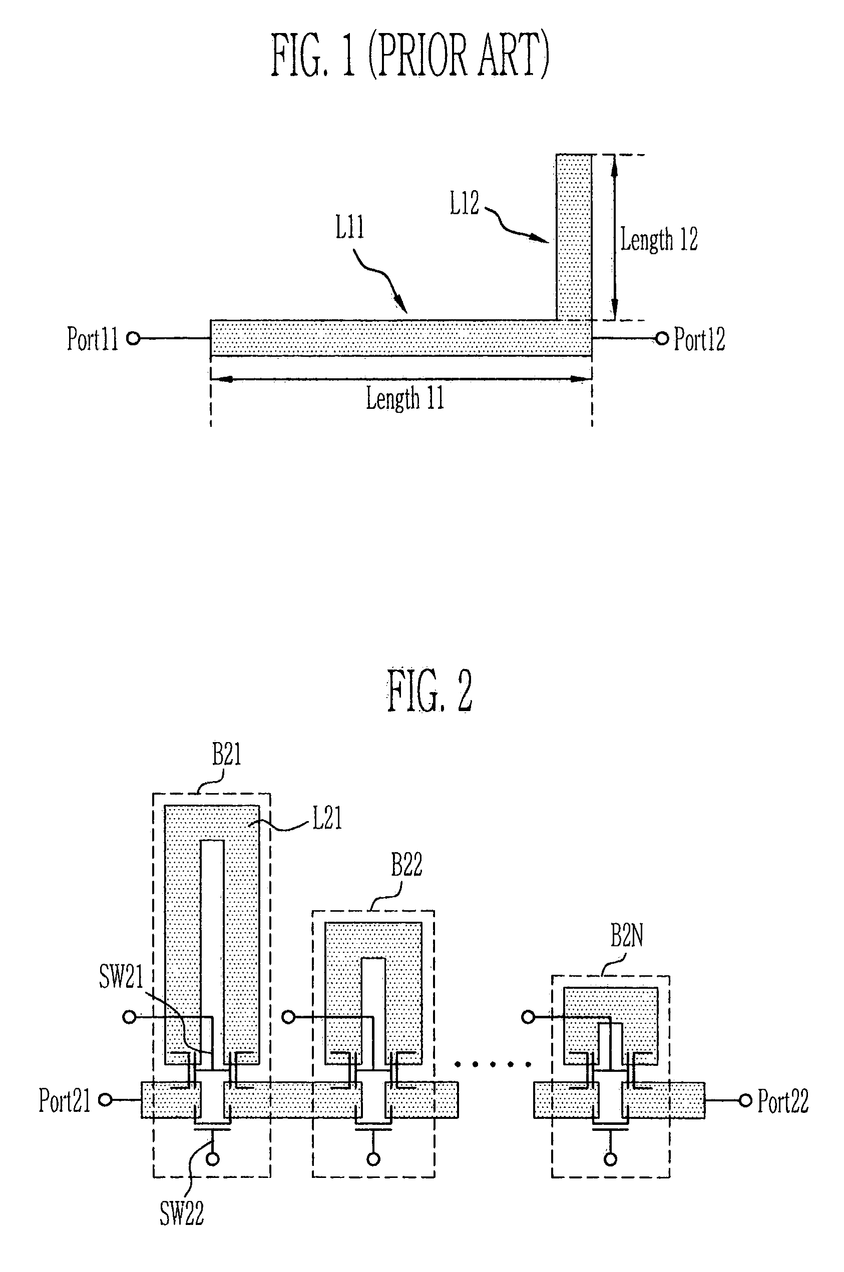
[0023] FIG. 2 shows transmission lines capable of varying electrical lengths. Referring to FIG. 2, the transmission lines can vary electrical lengths by changing the electrical paths of radio frequency signals by means of switches. Typically, a micro-strip line, which is a transmission line, formed on a substrate can have a predetermined thickness as shown in FIG. 2, and the electrical characteristic thereof can be changed in accordance with the width. The circuit as shown in FIG. 2 acts as a phase shifter in view of a fixed frequency. The transmission lines, capable of varying electrical lengths shown in FIG. 2, comprise 1 to N variable transmission line blocks. A first variable transmission line block B21 comprises switches SW21, SW22, and a transmission line L21. The switches SW21 and SW22 can be implemented as MOS transistors or PIN diodes which can function as switch, and the transmission line L21 has an electrical length .theta. 21. Other variable transmission line blocks B22,...


PUM


Abstract

The present invention is directed to a circuit capable of matching variable impedances, and implements the variable impedance matching circuit by varying an electrical length of a transmission line by means of external control signals. In the L or pi type matching circuit using inductance and capacitance as lumped elements, the variable impedance matching circuit is implemented by changing impedance values of the variable inductance and variable capacitance as lumped elements which have been made to be controlled, or by changing a topology of a circuit network by external control signals. Therefore, the variable impedance matching circuit according to the present invention enables it possible to electrically control an impedance of interest from arbitrary impedances, thereby a radio frequency circuit to which the variable impedance matching circuit belongs can be controlled, and the matching circuit can be implemented with arbitrary complex loads from any RF signal sources.

Description

FIELD OF THE INVENTION[0001] The present invention relates to an impedance matching circuit of a radio frequency circuit, in particular, to a variable impedance matching circuit capable of variably matching RF impedances in accordance with control signals.DESCRIPTION OF THE PRIOR ART[0002] In a radio frequency circuit, the matching circuit acts to transmit signals from one unit block to other one without an echo back (reflection of incident signal.) The conventional methods for implementing such a matching circuit have been disclosed. One of them is a method of using micro-strip lines and stubs, another is a method of implementing the matching .pi. or L type circuit using lumped elements: capacitances, inductances.[0003] The former has used micro-strip lines and stubs at fixed electrical lengths, and the latter has been implemented the matching circuit with fixed topology using inductance and capacitance; the matching circuit could not be changed once it has been implemented.[0004] ...

Claims


Application Information

Patent Timeline
Patent Type & Authority Applications(United States)
IPC IPC(8): H01P1/185H03H7/38H01P5/02
CPCH01P5/028H01P1/185H03H7/38
Inventor PARK, PIL JAEKIM, CHEON SOOPARK, MUN YANG
Owner ELECTRONICS & TELECOMM RES INST
Why Eureka
Try Eureka