
Lighting structure

a technology of lighting structure and light, applied in the direction of lighting support devices, fixed installations, lighting and heating apparatus, etc., can solve the problems of troublesome lighting assembly and high and achieve the effect of reducing the total cost of lighting manufacture and increasing productivity

Inactive Publication Date: 2004-06-03
GINGKO INDAL
View PDF12 Cites 21 Cited by
  • Summary
  • Abstract
  • Description
  • Claims
  • Application Information

AI Technical Summary

Benefits of technology

[0007] It is another object of the invention to provide a lighting structure that a lamp head and a power line are assembled / dissembled with ease to increase the productivity, a supporting rod used in the lighting structure can be applied to various type of lamp head, thereby the total cost of lighting manufacture being reduced.

Problems solved by technology

Furthermore, since the power line has to be arranged in the supporting rods, assembly of lighting is troublesome.
Therefore, the total cost of lighting manufacture is high.

Method used


Image

  • Lighting structure
  • Lighting structure
  • Lighting structure

Examples


Embodiment Construction

[0020] Wherever possible in the following description, like reference numerals will refer to like elements and parts unless otherwise illustrated.

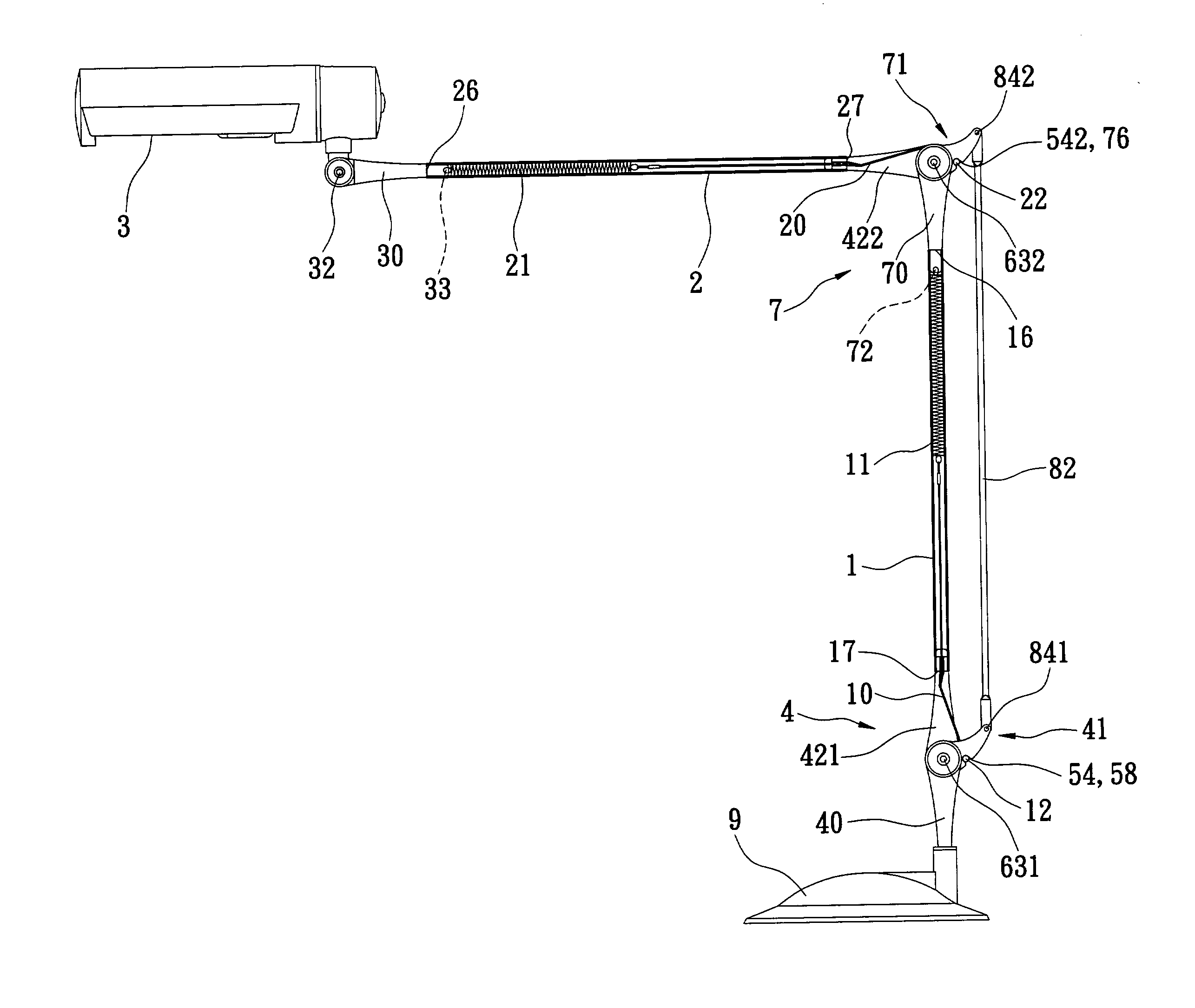
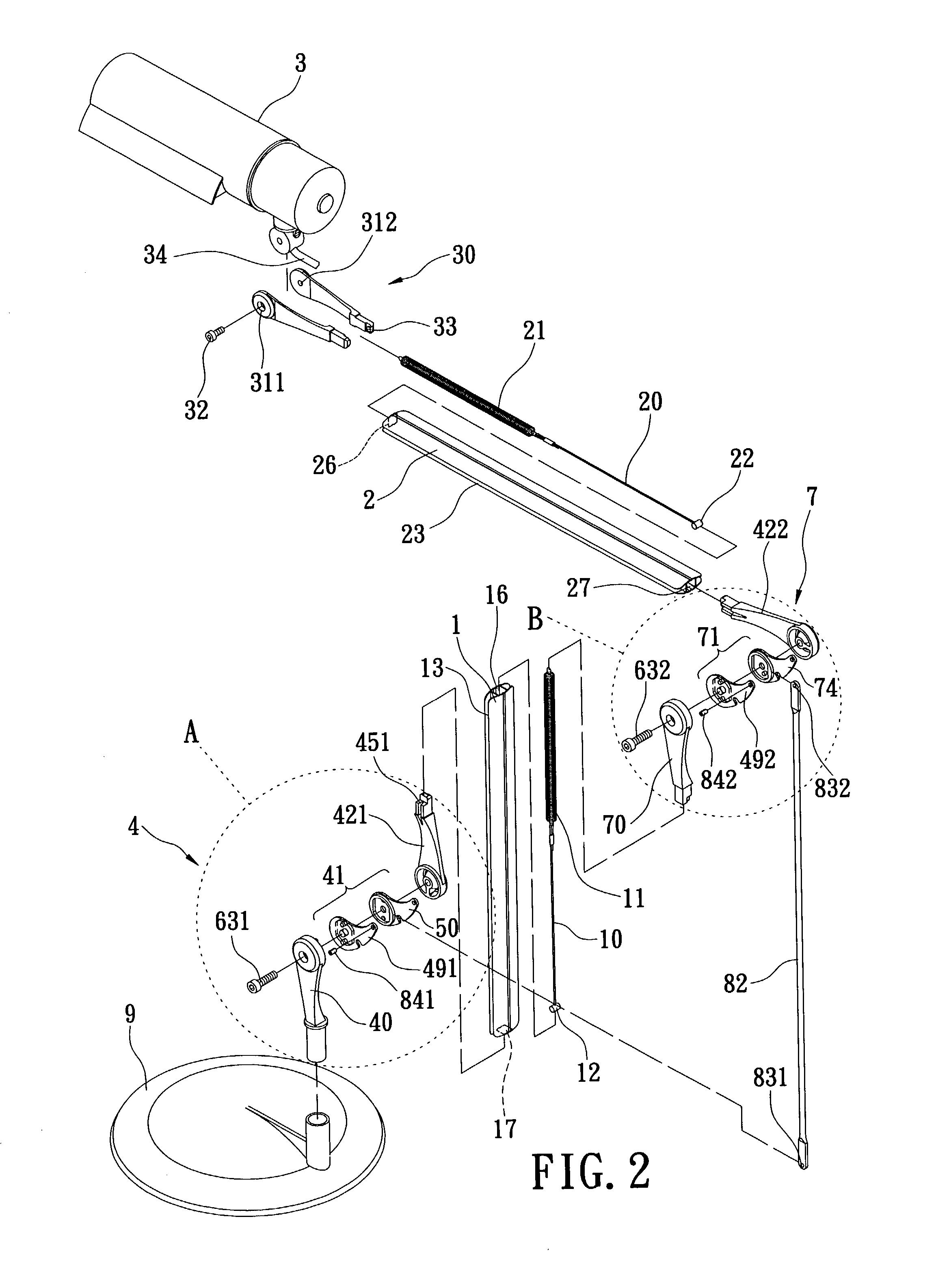
[0021] Referring to FIG. 2 through FIG. 4, a lighting structure includes a wire collector, a lamp head 3, a base 9, and a balancing device.

[0022] The wire collector includes a first supporting rod 1 and a second supporting rod 2, which are, for example, integrally formed in a single body. The first supporting rod 1 has a channel 13 that includes a top opening 14 and a bottom 15, as shown in FIG. 5. A diameter of the top opening 14 is smaller than a width of the bottom 15. The second supporting rod 2 has the same structure as the supporting rod 1. Furthermore, the first supporting rod 1 has a first front opening 16 and a first tail opening 17. The second supporting rod 2 has a second front opening 26 and a second tail opening 27.

[0023] The lamp head 3 has a bulb therein (not shown) which is electrically connected to a power line 34. The pow...


PUM


Abstract

A lighting structure includes a wire collector, a lamp head, a base and a balancing device. The wire collector includes a first supporting rod and a second supporting rod which are respectively integrally formed. The balancing device includes a first hinge, a first cord, a first elastic element, a second hinge, a second cord and a second elastic element. The first and second hinges respectively drive the first and second cords to tense or release the first and second elastic elements, while the first and second elastic elements hold the first and second supporting rods. A channel is formed on each of the first and second supporting rods for receiving a power line.

Description

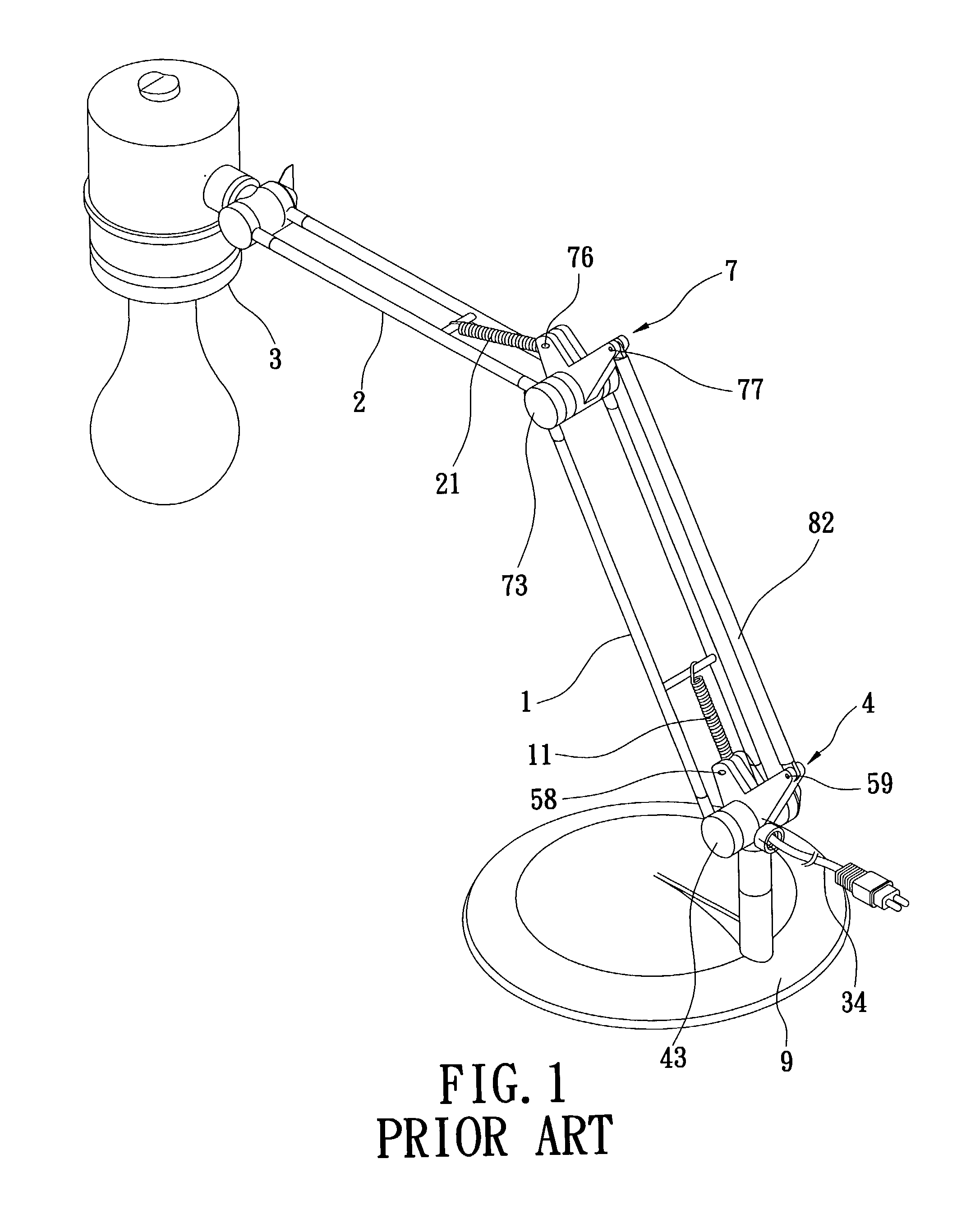
[0001] 1. Field of the Invention[0002] The invention relates to a lighting structure and, more particularly, to an adjustable lighting structure having a balancing device and a wire collector.[0003] 2. Description of the Related Art[0004] A lighting, such as a desk lamp, always has an adjustable lamp. Referring to FIG. 1, a lighting includes a first supporting rod 1, a second supporting 2, a lamp head 3, a base 9 and a balancing device. The balancing structure includes a first hinge 4, a first spring 11, and a second spring 21. The first hinge 4 and the second hinge 7 are respectively provided with joints 43, 73, spring contacts 58, 76, and connecting rod contacts 59, 77. The joint 43 of the first hinge 4 is pivotally connected to a bottom of the first supporting rod 1. An upper end and a lower end of the first, spring 11 are respectively connected to the first supporting rod 1 and the spring contact 58 of the first pivot 4. The joint 73 of the second hinge 7 is pivotally connected ...

Claims


Application Information

Patent Timeline
Patent Type & Authority Applications(United States)
IPC IPC(8): F21S6/00F21V21/28F21V27/00
CPCF21S6/003F21V27/00F21V21/28
Inventor CHEN, WEN-TSUNG
Owner GINGKO INDAL
Learn More