

Wireless LAN technologies for reducing interference between or among wireless LAN access points
a technology of wireless lan and access point, which is applied in the direction of polarisation/directional diversity, wireless commuication services, and differential interacting antenna combinations, etc., can solve the problems of reducing the number of communication channels in accordance with the ieee 802.11 protocol, and reducing the number of effective channels of wireless lan technologies
- Summary
- Abstract
- Description
- Claims
- Application Information
AI Technical Summary
Benefits of technology
Problems solved by technology
Method used
Image

Examples
first embodiment
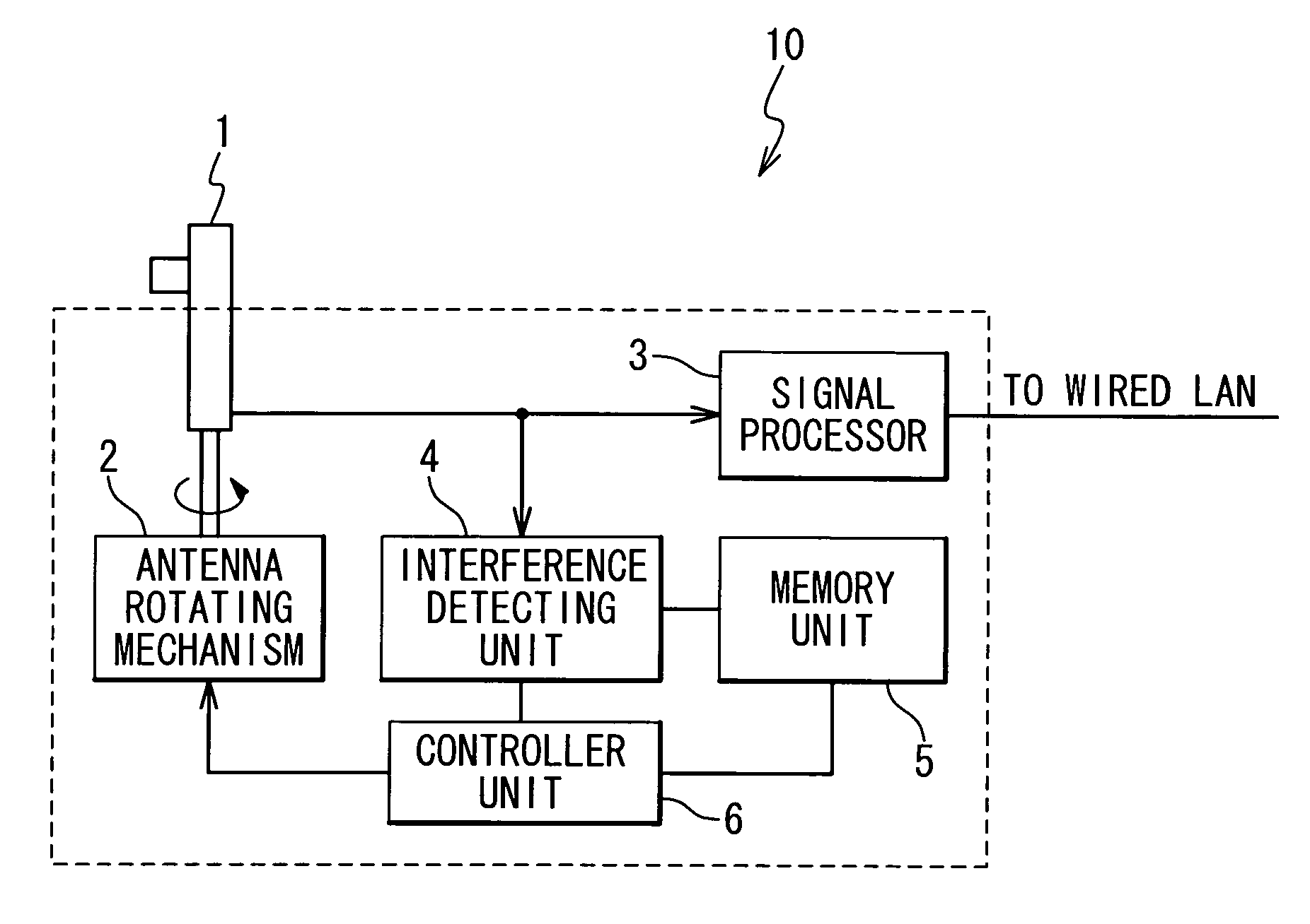
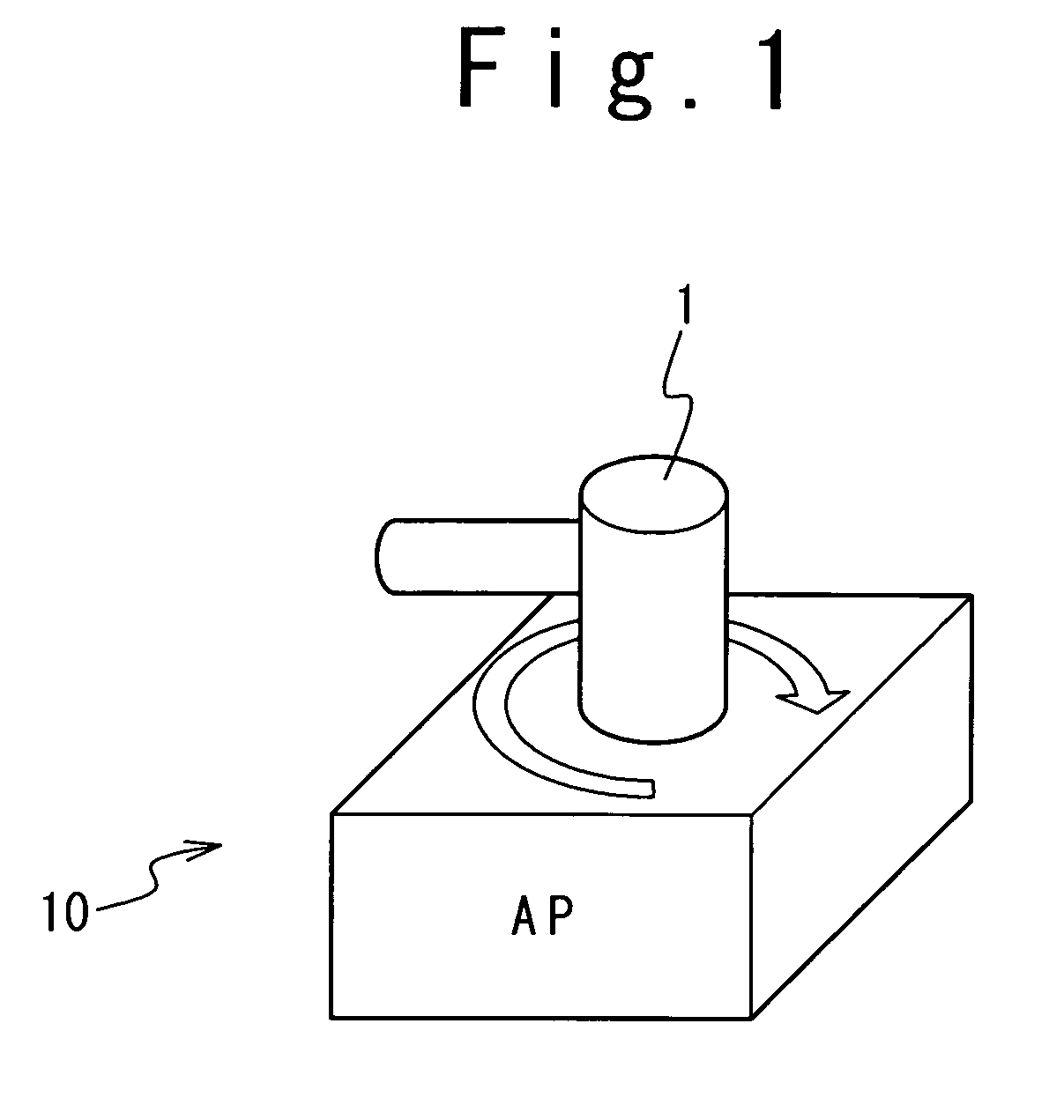
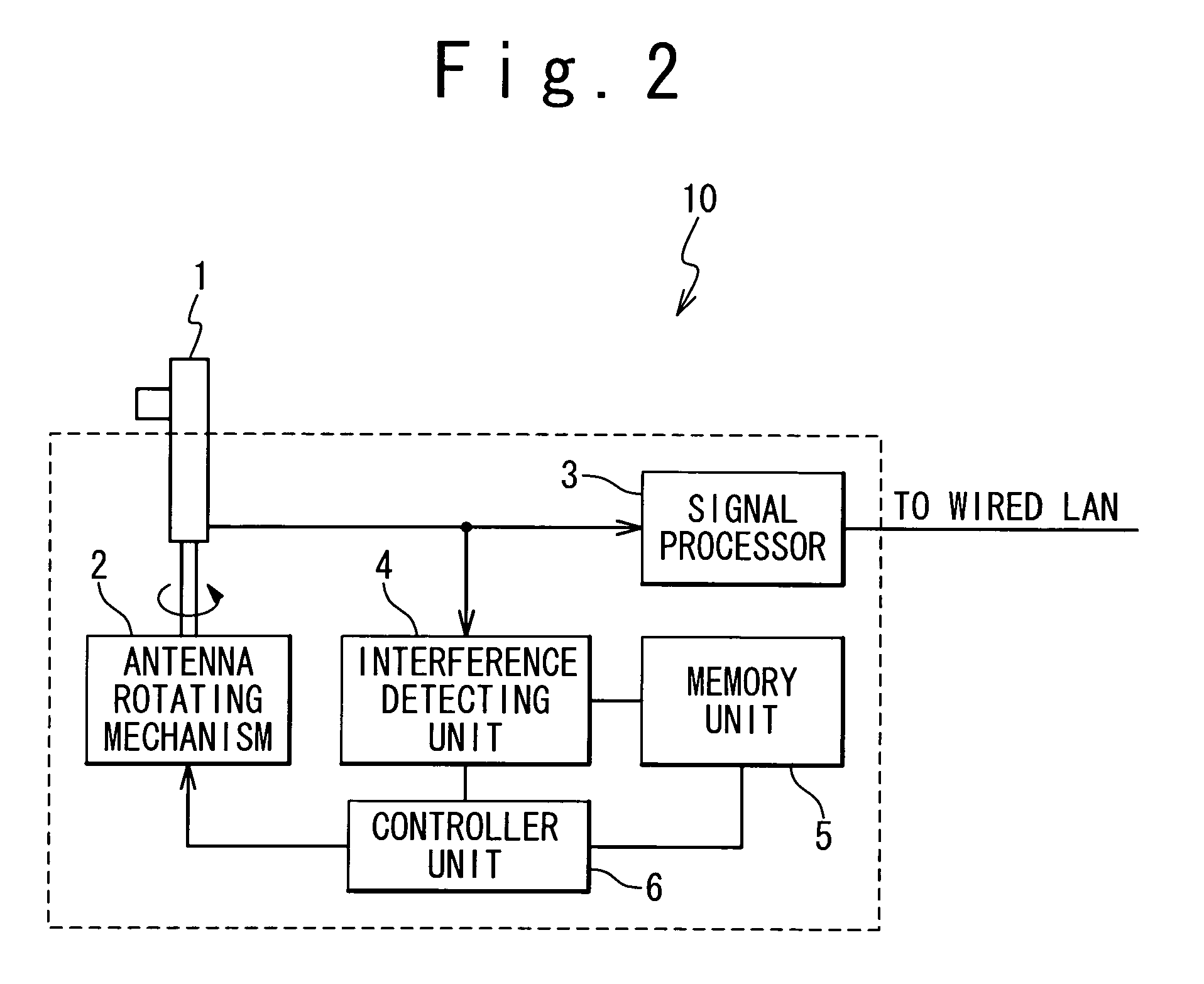
[0044] In a first embodiment, as shown in FIG. 1, a wireless LAN access point 10 is provided with a directional antenna 1. As shown in FIG. 2, the directional antenna 1 is coupled to an antenna rotating mechanism 2. The antenna rotating mechanism 2 is adapted to rotate the directional antenna 1, and to thereby adjust the maximum gain direction of the directional antenna 1.
[0045] The directional antenna 1 is electrically connected to a signal processor 3. The signal processor 3 communicates with a wireless LAN adapter (not shown) through the directional antenna 1 using the IEEE 802.11 protocols. The signal processor 3 is connected to a wired LAN, and provides accesses to the wired LAN for an electronic apparatus connected to the wireless LAN adapter. A laptop computer exemplifies the electronic apparatus connected to the wireless LAN adapter.
[0046] The directional antenna 1 is also connected to an interference detecting unit 4 determining whether the antenna 1 receives interference f...
second embodiment
[0056] In a second embodiment, as shown in FIG. 4, a wireless LAN access point 20 is provided with a directional antenna 11 and an omnidirectional antenna 12. As shown in FIG. 5, the directional antenna 11 is connected to an antenna rotating mechanism 13 to adjust the gain maximum direction thereof to an optimized direction.
[0057] The directional and omnidirectional antenna 11 and 12 are connected to a selector 14. The selector 14 selects one of the directional and omnidirectional antenna 11 and 12, and electrically connects the selected antenna to a signal processor 15.
[0058] The signal processor 15 communicates with a wireless LAN adapter (not shown) through the antenna selected by the selector 14 using the IEEE 802.11 protocols. The signal processor 15 is connected to a wired LAN, and provides accesses to the wired LAN for an electronic apparatus connected to the wireless LAN adapter.
[0059] The selector 14 is also connected to an interference detecting unit 16 determining whether...
third embodiment
[0072] In a third embodiment, as shown in FIG. 6, a wireless LAN access point 30 is provided with a plurality of directional antennas 21 (two shown), which may be distinguished by indexes attached thereto.
[0073] As shown in FIG. 7A, the gain maximum directions of the directional antennas 21.sub.1, 21.sub.2, . . . are different from one another. That is, communicable areas 25.sub.1, 25.sub.2, . . . of the respective directional antennas 21.sub.1, 21.sub.2, . . . have their longitudinal axes in different directions. The gain maximum directions of the directional antennas 21 are determined such that the communicable area of the wireless LAN access point 30 is maximized.
[0074] As shown in FIG. 6, the directional antennas 21 are connected to a signal processor 22. The signal processor 22 communicates with a wireless LAN adapter (not shown) through the directional antennas 21 using the IEEE 802.11 protocols. The signal processor 22 is connected to a wired LAN, and provides accesses to the...
PUM
 Abstract
Description
Claims
Application Information