Flow control valve

a flow control valve and valve body technology, applied in the direction of valve operating means/release devices, process and machine control, instruments, etc., can solve the problem of difficulty in the flow control valve to perform the pressure compensation function

Active Publication Date: 2004-06-10
SHIMADZU CORP
View PDF5 Cites 3 Cited by
  • Summary
  • Abstract
  • Description
  • Claims
  • Application Information

AI Technical Summary

Problems solved by technology

As a result, it is difficult for the flow contro...

Method used


Image

  • Flow control valve
  • Flow control valve
  • Flow control valve

Examples


Embodiment Construction

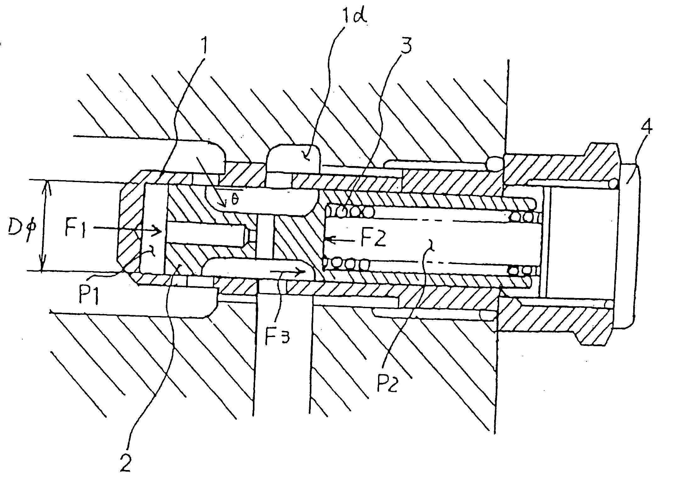
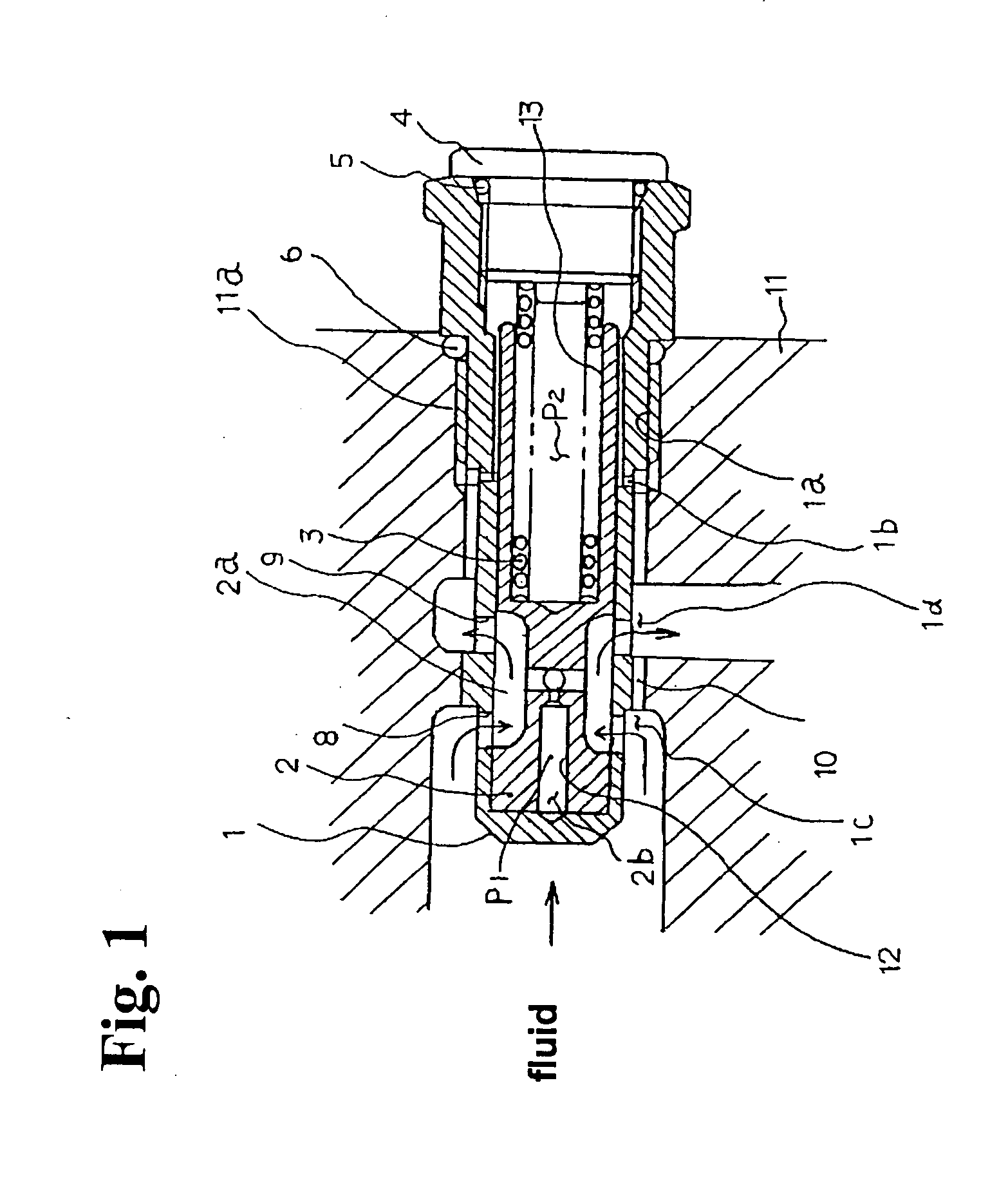
[0018] Hereunder, embodiments of the present invention will be described with reference to the accompanying drawings. FIG. 1 is a vertical sectional view showing a structure of a flow control valve according to an embodiment of the present invention. The flow control valve is to be built in a chassis block 11 of a hydraulic power unit (not shown). A spool 2 is fitted into a cylindrical body 1 to be movable in an axial direction and a spring 3 is inserted in a cylindrical portion of the spool 2. One end of the spring 3 elastically contacts the cylindrical portion of the spool 2, and the other end thereof elastically contacts an inner end surface of a plug 4 screwed to a screw portion 1a of the body 1.

[0019] The body 1 includes the screw portion 1a to be screwed into a screw portion 11a formed in the chassis block 11; a pinhole 1b for filling a fluid into a large diameter portion 13 including the spring 3; an input port 1c formed of a plurality of orifices 8 arranged on a same circle ...


PUM


Abstract

In a flow control valve, a spool is fitted into a cylindrical body including an input port and an output port. A spring is disposed between the spool and a flow rate setting plug at an end of the cylindrical body. A flow by-path communicating with the input port and the output port is provided on an outer peripheral portion of the cylindrical body. When a quantity of a fluid flowing through the flow control valve is reduced, the fluid flowing through the flow by-path compensates the reduction thereof. Accordingly, it is possible to maintain a constant flow rate.

Description

BACKGROUND OF THE INVENTION AND RELATED ART STATEMENT[0001] The present invention relates to a flow control valve used for various industrial instruments, for example, a hydraulically control apparatus, such as a vehicle and a forklift.[0002] Japanese Patent Publication (KOKAI) No. 5-204465 has disclosed conventional pressure compensation type flow control valves as shown in FIGS. 6 and 7. The flow control valve shown in FIG. 6 has a structure in which a spool 22 is slidably fitted in a cylindrical body 21, and a spring 24 is disposed between the spool 22 and a control screw portion 23 screwed to a base end of the body 21. When a fluid flows from an inflow port 26 to an outflow port 25 along an arrow in FIG. 6, the spool 22 performs a pressure-compensation operation for automatically controlling an opening of a throttle portion 22a formed between the spool 22 and the body 21. Accordingly, the fluid flows out of the outflow port 25 at a constant rate corresponding to an opening of a ...

Claims


Application Information

Patent Timeline
IPC IPC(8): F16K17/28G05D7/01
CPCG05D7/0133Y10T137/7613Y10T137/7788Y10T137/7793
Inventor KUROMUSHA, JUNYAYAMASHITA, SHIGERU
Owner SHIMADZU CORP
Why Eureka
Try Eureka