Liquid ejecting head and liquid ejecting apparatus

a liquid ejecting and liquid ejecting technology, which is applied in printing and other directions, can solve the problems of degrading the performance of the bubble discharging head and not only in the ink jet printing head, and achieve the effect of suppressing preventing the degradation of the bubble discharging performance, and facilitating maintenan

Active Publication Date: 2011-09-22
SEIKO EPSON CORP
View PDF9 Cites 3 Cited by
  • Summary
  • Abstract
  • Description
  • Claims
  • Application Information

AI Technical Summary

Benefits of technology

[0011]With such a configuration, the sandwiching portion including the first and second supply members and sandwiching the filter includes the inclination portion that is inclined to the downstream side so as to face the outside of the liquid supply path. Accordingly, in the liquid ejecting head of the aspect, it is possible to allow the filter to protrude toward the first liquid supply path, and thus to suppress a degradation of the bubble discharging performance by preventing the filter from being deformed toward the inner wall surface of the second liquid supply path. In addition, since a gap between the filter and the inner wall surface is not narrowed, it is possible to supply a sufficient amount of liquid to bubbles that tend to stay at the position therebetween. Therefore, bubbles tend not to assemble around the circumference of the channel area of the filter.
[0012]The filter may include a channel area and a sandwiching area sandwiched by the first and second supply members. An inner wall surface facing the channel area in the second liquid supply path may be provided with a protrusion member that protrudes toward the first liquid supply path. Accordingly, since the filter can be supported by the protrusion member even when the filter is depressed toward the second liquid supply path, it is possible to suppress a degradation of the bubble discharging performance.
[0013]Here, the protrusion member may protrude toward the first liquid supply path past a surface sandwiching the filter. Since the filter protrudes toward the first liquid supply path and the protrusion state is easily maintained, it is possible to suppress a degradation of the bubble discharging performance.
[0014]Further, an inner wall surface facing the channel area in the first liquid supply path may be provided with a regulation member that protrudes toward the filter and regulates the filter from the upstream side. Since the regulation member is provided, it is possible to prevent the filter from being excessively deformed toward the first liquid supply path.
[0015]The distance between a surface facing a surface sandwiching the filter in the second liquid supply path, and the surface sandwiching the filter may be uniform. With such a configuration, even when the filter is deformed toward the first liquid supply path, it is possible to maintain the flow rate of the ink.
[0016]A liquid ejecting apparatus includes the liquid ejecting head. Since the liquid ejecting head suppressing a degradation of the bubble discharging performance is provided, it is possible to obtain desired liquid ejecting characteristics.

Problems solved by technology

In this case, when the filter is deformed and depressed toward the inner wall surface of the channel on the downstream side of the filter, the filter may adhere to the inner wall surface or the deformed filter may block the channel during a cleaning process of performing a bubble discharging operation in which suction is performed through a large negative pressure, which causes a problem in that the bubble discharging performance is degraded.
Further, there is a problem in that the filter is twisted to adhere to the inner wall surface of the channel on the downstream side of the filter or bubbles tend to assemble between the twisted filter and the inner wall surface of the channel or the like on the downstream side of the filter.
Further, these problems occur not only in the ink jet printing head, but also in a liquid ejecting head ejecting liquids other than ink.
In addition, since a gap between the filter and the inner wall surface is not narrowed, it is possible to supply a sufficient amount of liquid to bubbles that tend to stay at the position therebetween.

Method used


Image

  • Liquid ejecting head and liquid ejecting apparatus
  • Liquid ejecting head and liquid ejecting apparatus
  • Liquid ejecting head and liquid ejecting apparatus

Examples


first embodiment

[0027

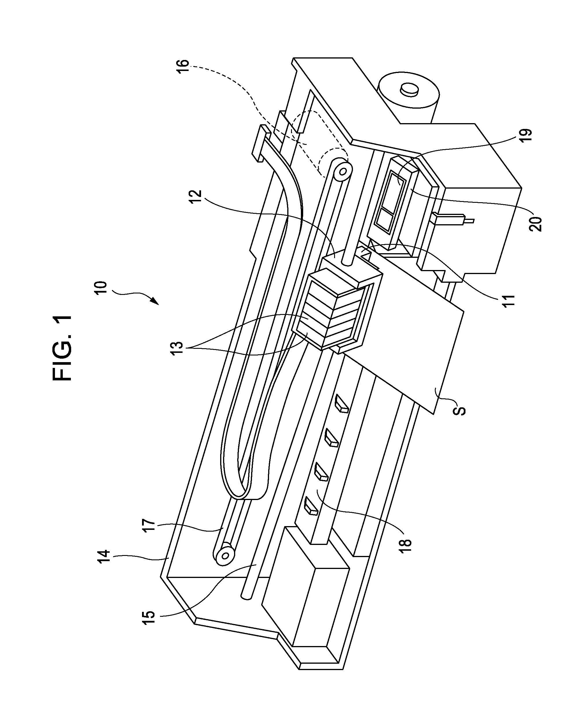
[0028]FIG. 1 is a schematic perspective view illustrating an ink jet printing apparatus which is an example of a liquid ejecting apparatus according to a first embodiment of the invention. As shown in FIG. 1, an ink jet printing apparatus 10 of the invention has a configuration in which an ink jet printing head (hereinafter, referred to as a printing head) 11 as an example of a liquid ejecting head ejecting an ink droplet is fixed to a carriage 12, and an ink cartridge 13 as an example of a liquid storing member storing plural inks having different colors such as black (B), light black (LB), cyan (C), magenta (M), and yellow (Y) are attachably / detachably fixed to the printing head 11.

[0029]The carriage 12 having the printing head 11 mounted thereon is provided in a carriage shaft 15 attached to an apparatus body 14 so as to be movable in the axial direction. Then, when a driving force of a driving motor 16 is transmitted to the carriage 12 via plural gears (not shown) and a tim...

second embodiment

[0064

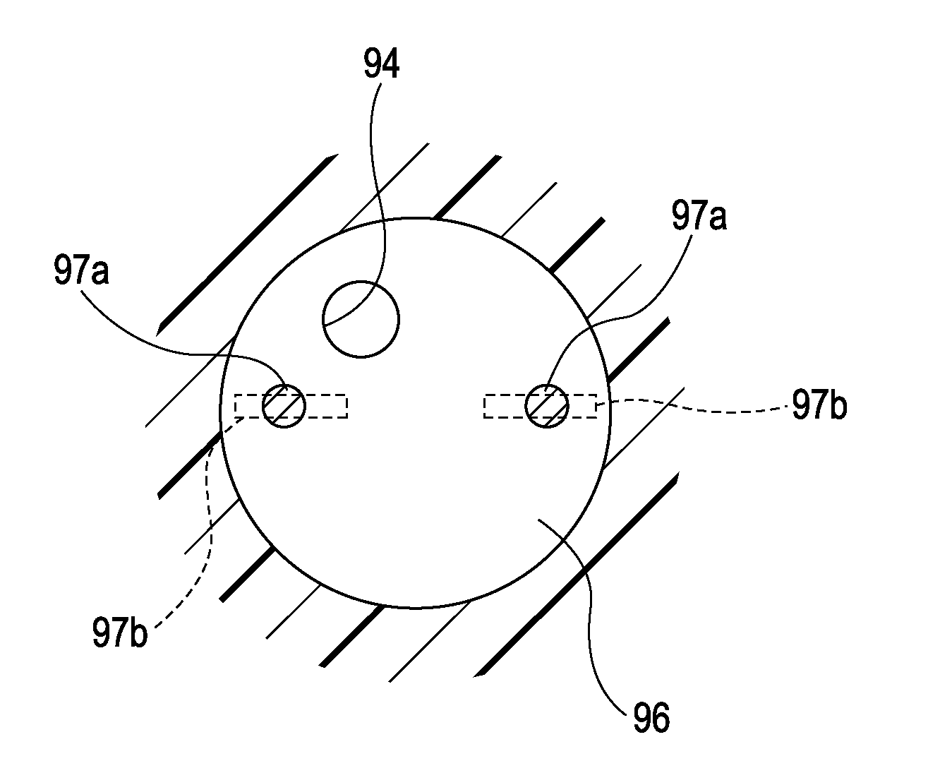
[0065]In the embodiment, the ink jet printing head 11 according to the first embodiment further includes protrusions (protrusion members 97a and regulation members 97b) which are formed in the first and second ink supply paths 91 and 92. Hereinafter, the embodiment will be described in detail with reference to FIGS. 7 and 8.

[0066]In the embodiment, the inner wall surface 96 of the cartridge casing 32 is provided with two protrusion members 97a protruding toward the ink supply needle 31 more than the bonding plane P. Each protrusion member 97a is a column-shaped protrusion, and supports the channel area 33b of the filter 33 from the downstream side thereof. By providing the protrusion member 97a, not only the inclination portion 38a but the channel area 33b of the filter 33 is lifted toward the ink supply needle 31 more than the bonding plane P by the protrusion member 97a, and the filter 33 is more reliably formed in a convex shape toward the ink supply needle 31. Likewise, sin...


PUM


Abstract

A liquid ejecting head includes: a head body which ejects a liquid supplied from a liquid storing member via a liquid supply path; a first supply member which is provided with a first liquid supply path forming a part of the liquid supply path; a second supply member which is provided with a second liquid supply path communicating with the first liquid supply path and forming a part of the liquid supply path, and which supplies the liquid to the head body; and a filter which is sandwiched between the first and second liquid supply paths, wherein a sandwiching portion including the first and second supply members and sandwiching the filter includes an inclination portion that is inclined to the downstream side so as to face the outside of the liquid supply path. A liquid ejecting apparatus includes the liquid ejecting head.

Description

[0001]The entire disclosure of Japanese Patent Application No: 2010-065279, filed Mar. 19, 2010 are expressly incorporated by reference herein.BACKGROUND[0002]1. Technical Field[0003]The present invention relates to a liquid ejecting head and a liquid ejecting apparatus ejecting a liquid, and particularly, to an ink jet printing head and an ink jet printing apparatus ejecting ink as a liquid.[0004]2. Related Art[0005]In an ink jet printing head as a representative example of a liquid ejecting head, ink is supplied from an ink cartridge as a liquid storing member filled with the ink to a head body via an ink supply needle which is attachably or detachably inserted to the ink cartridge or disposed at a front end of a supply tube such as a tube extending from the ink cartridge, and an ink supply path which is formed in a supply member such as a cartridge casing holding the ink cartridge. Then, a pressure generating member such as a piezoelectric element provided in the head body is dri...

Claims


Application Information

Patent Timeline
Patent Type & Authority Applications(United States)
IPC IPC(8): B41J2/175
CPCB41J2/14233B41J2002/14403B41J2002/14362
Inventor KOBAYASHI, HIROYUKIKANAYA, MUNEHIDEOKUBO, KATSUHIROUJI, NOBUYOSHINAKAMURA, KAZUHIDE
Owner SEIKO EPSON CORP
Why Eureka
Try Eureka