Rainwater tank cleaning system

Inactive Publication Date: 2004-06-10
AGNEW WARREN ROY
View PDF0 Cites 8 Cited by
  • Summary
  • Abstract
  • Description
  • Claims
  • Application Information

AI Technical Summary

Benefits of technology

0038] In FIG. 3 is shown an exploded view of the small holes 18 formed in outlet pipe 3 at 17, to prevent a siphoning effect from

Problems solved by technology

A problem associated with rainwater stored in a tank is a build-up of sediment and plant material, which has been carried off the roof along the spouting by the rainwater, and into the storage tank.
The process of decay can significantly lower the available oxygen in the water.
These devices do not however prevent smaller particles such as seeds, pollen, road dust, sand and broken parts of leaves and sticks etc from accumulating in

Method used


Image

  • Rainwater tank cleaning system
  • Rainwater tank cleaning system
  • Rainwater tank cleaning system

Examples


working example 2

[0040] In a similar manner to Example 1 the invention was trialed on a 4,000 gallon rainwater tank. The only difference was that an 80 mm PVC water pipe was used rather than the 40 mm PVC pipe. Again six holes were drilled in the pipe and sediment was added to the tank. When the tank was caused to overflow, the sediment was drawn out of the tank through the holes in the pipe.

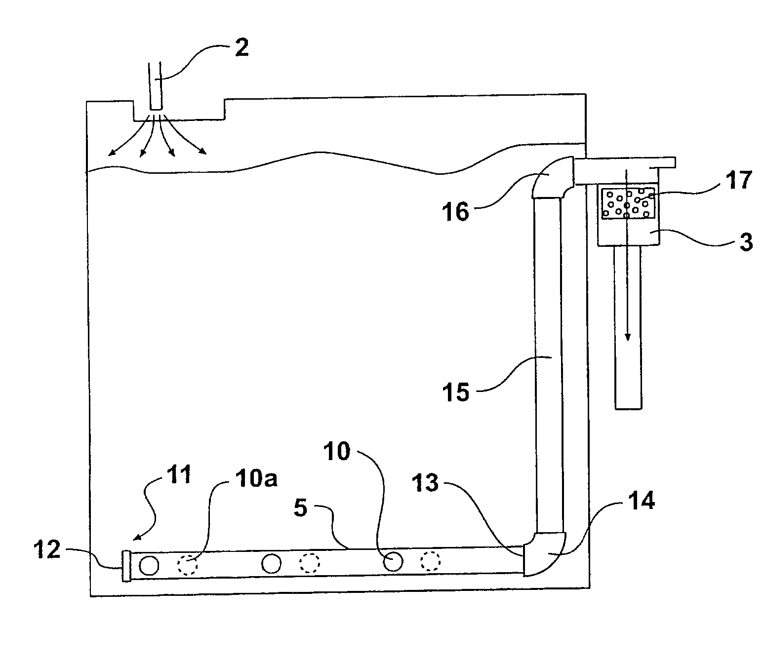
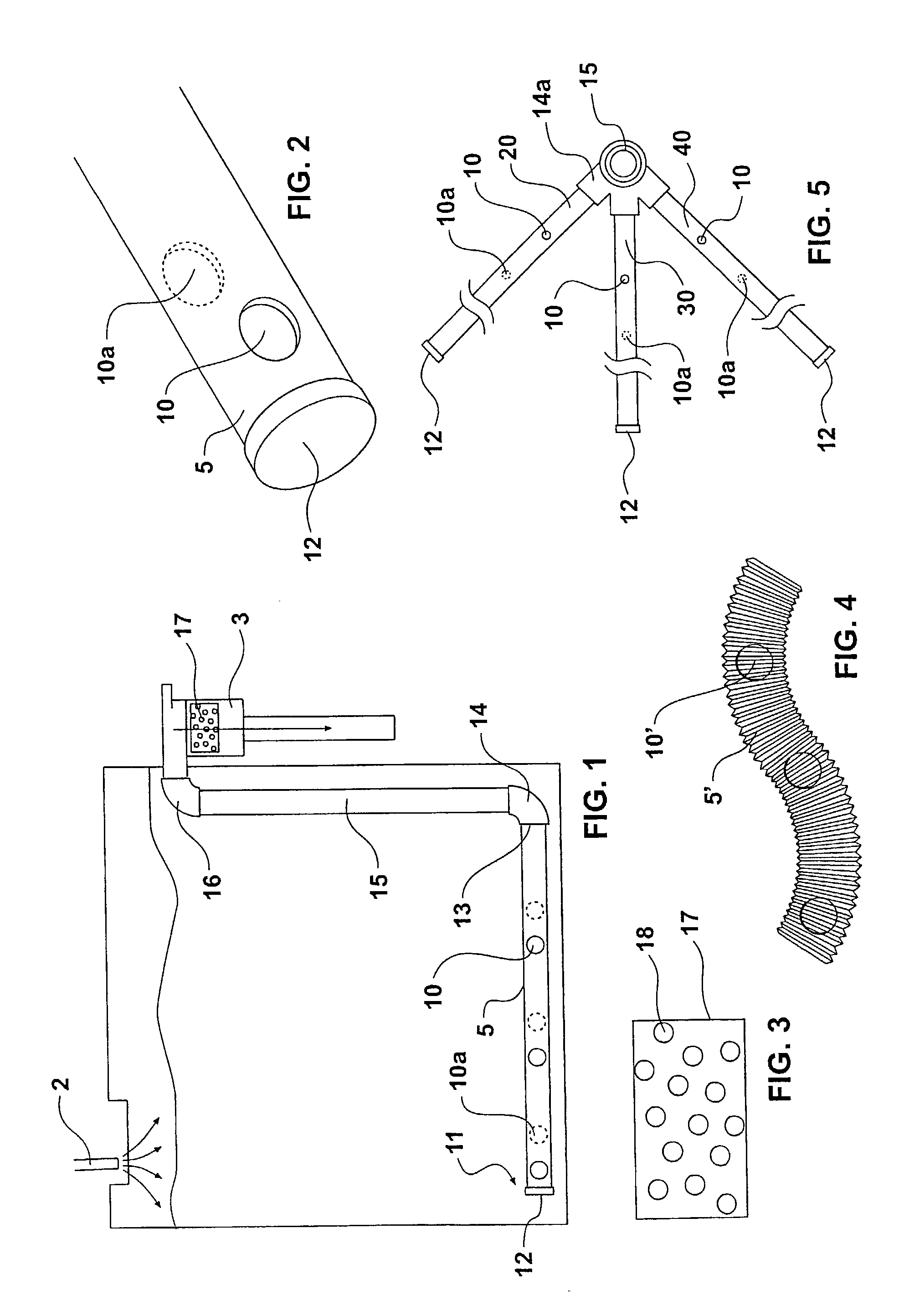
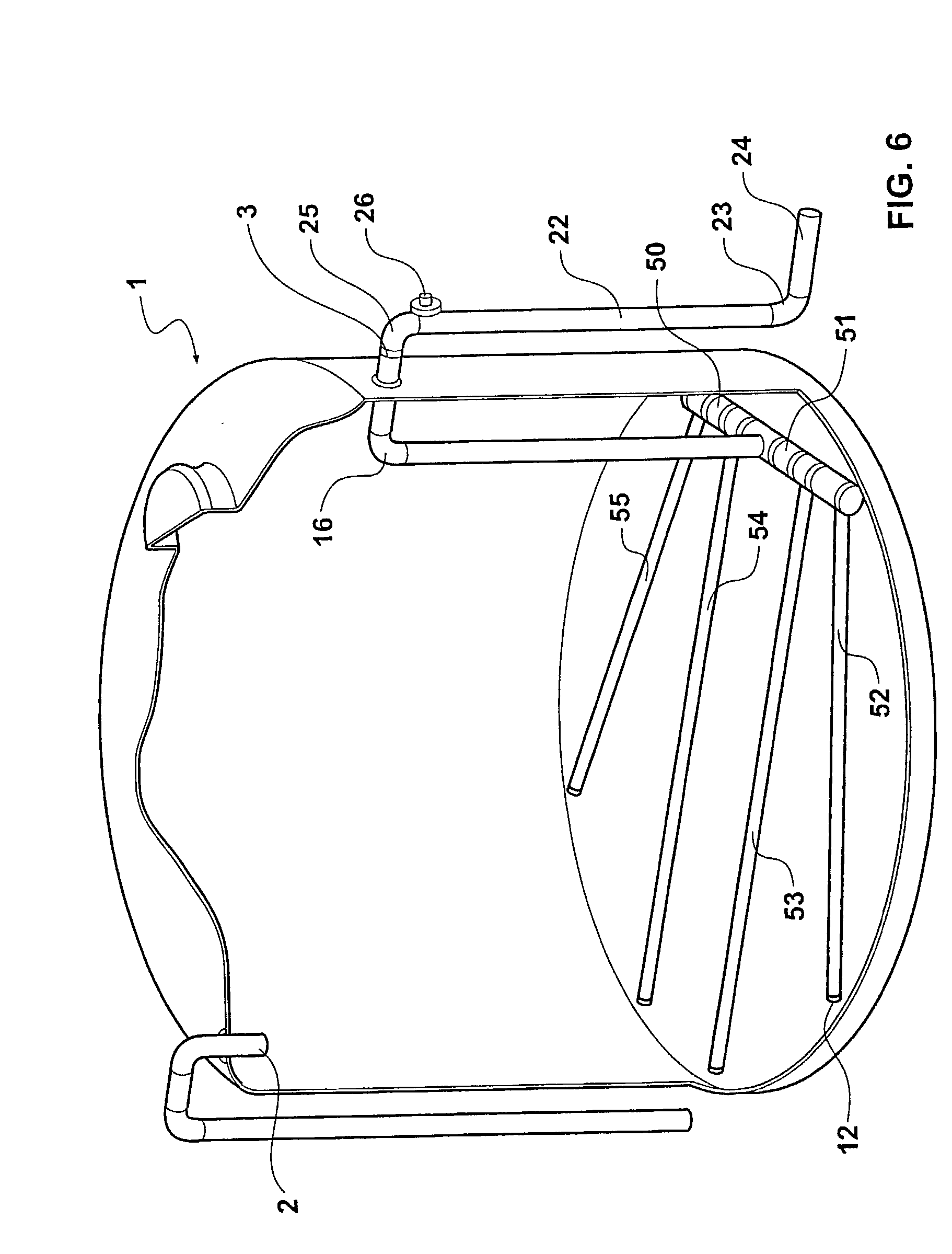
[0041] When water flows from the house roof and enters the inlet 2 of the tank; rather than flowing directly through the outflow 3, the tank-vac.TM. system causes the water at the base of the tank to enter the holes 10 and 10a located in the pipes at the base of the tank 1. The water entering the holes 10 and 10a in the pipe 5 draws in the sediment, plant material, dirt and other particulate solids on the base of the storage tank and by siphon action washes them out through the overflow 3. In this way the fresh water entering the tank is not immediately removed by the overflow and the tank is automatically clean...


PUM

PropertyMeasurementUnit
Surface areaaaaaaaaaaa

Abstract

A rainwater cleaning system for a water tank comprises a pipe member having a closed end located on the floor of the tank. The pipe member also has an open end connectable to an outflow from the tank. Located near the closed end of the pipe member is at least one hole. The surface area of the hole preferably equals the surface area of the outflow.

Description

[0001] In many households dependent on the collection of rainwater as a source of drinking water, the collection area is normally the house roof and the rainwater is stored in a tank that can be constructed of iron, polyethylene, or concrete and which is located on a level below and in close proximity to the house roof so that the water flows by gravity down the spouting and to the storage tank.[0002] Wind blown seeds, leaves, sticks, pollen, sand, road dust, bird droppings and dead insects etc can accumulate on the roof.[0003] A problem associated with rainwater stored in a tank is a build-up of sediment and plant material, which has been carried off the roof along the spouting by the rainwater, and into the storage tank.[0004] The sediment decaying, places an oxygen demand on the tank water. The process of decay can significantly lower the available oxygen in the water.[0005] There are devices to minimise the plant material which is carried off the roof. Devices such as screens th...

Claims


Application Information

Patent Timeline
IPC IPC(8): B01D21/24E03B3/03
CPCE03B3/03B01D21/245B01D21/0006Y02A20/00Y02A20/108
Inventor AGNEW, WARREN ROY
Owner AGNEW WARREN ROY
Why Eureka
Try Eureka