Under water lighted fishing lure

Inactive Publication Date: 2004-06-17
LINDGREN PETER B
View PDF67 Cites 16 Cited by
  • Summary
  • Abstract
  • Description
  • Claims
  • Application Information

AI Technical Summary

Benefits of technology

[0006] The underwater fishing lure includes, in one embodiment, a transparent housing, batteries (typically two) and two light emitting devices (LEDs), wherein each LED emits a different color light. Studies have shown that the use of a two color LED lighted lure greatly enhances fish catch. Particularly, when the lure includes a blue LED and a green LED, fish catch is more than double a white LED lure, a blue green LED lure or green LED lure. Although not as dramatic, a green and white LED pair also significantly increases fish catch. In another embodiment, the pair of LEDs are driven with a voltage at or above 3.3 volts. Typically this is established with the use of a pair of serially connected lithium batteries. A further embodiment of the present invention drives the LEDs at or above 125% of the recommended drive voltage for the LED or 150% over the maximum current. Studies have also shown that driving LEDs at higher voltages or currents significantly increases fish catch. Over driving LEDs increases the light intensity or lux output of the lure. Blinking circuits or cycling each LED ON and OFF also improves the lure. Other circuits cycle one LED ON and OFF at a different rate compared to the other LED. To achieve the same feature (cycles or blinking), a battery powered lighting fishing lure, generally shaped as a cylinder, may include, at one terminal end, a planar wing extending axially wherein the planar wing is large enough to turn the lure based upon underwater flows and currents. Further, a chemical luminescent lighted fishing lure, also configured as a cylinder, may include a planar wing extending from the terminal end which causes the lure to twist, turn and rotate based upon underwater flows and currents.

Problems solved by technology

Studies have also shown that driving LEDs at higher voltages or currents significantly increases fish catch.

Method used


Image

  • Under water lighted fishing lure
  • Under water lighted fishing lure
  • Under water lighted fishing lure

Examples


Embodiment Construction

[0024] The present invention relates to a lighted fishing lure and method therefor.

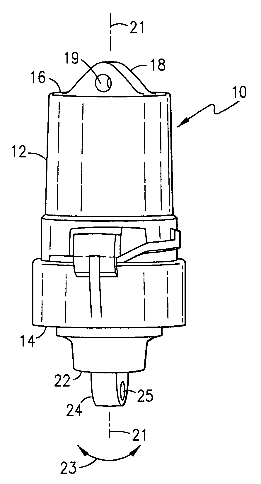
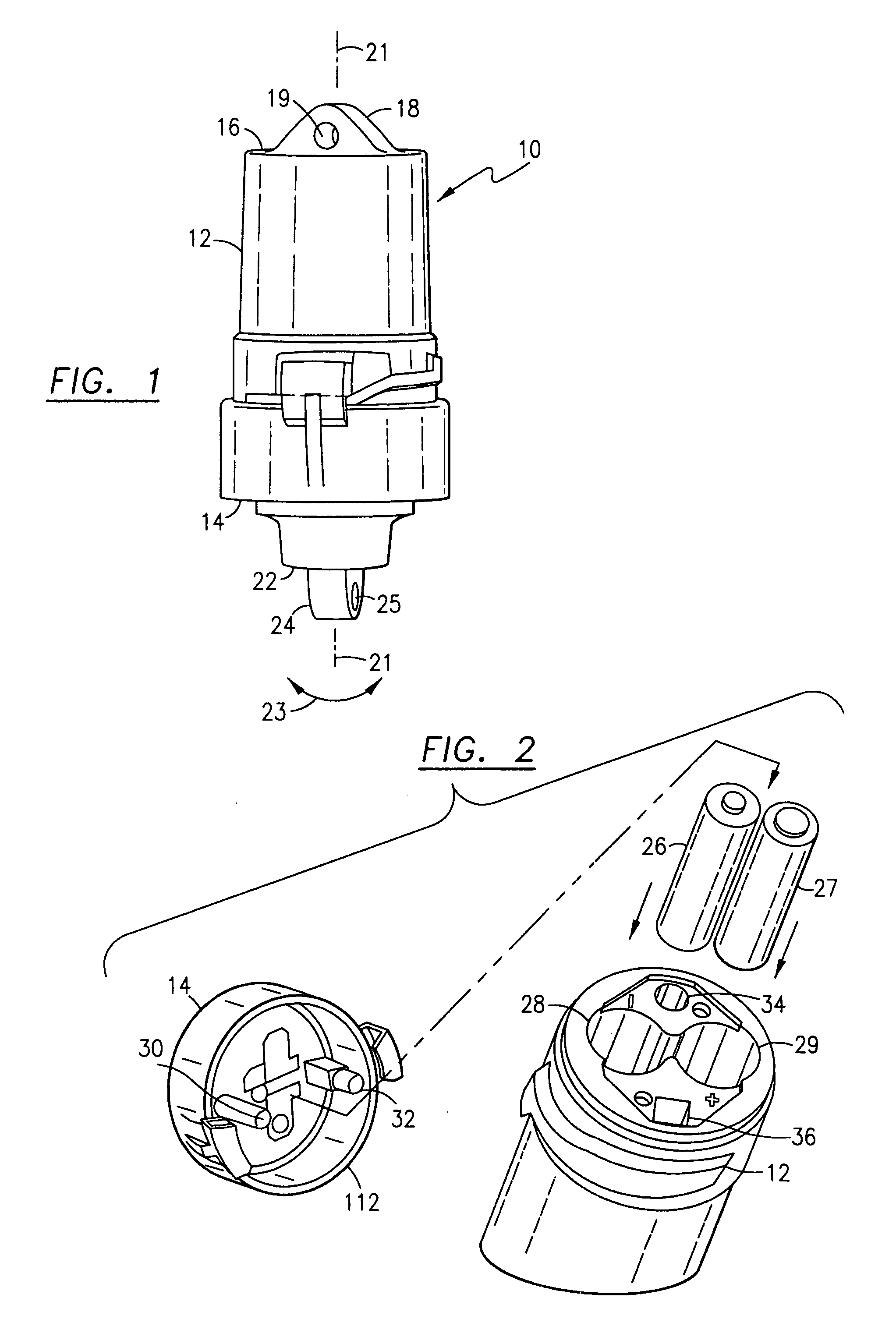
[0025] FIG. 1 diagrammatically illustrates lighted fishing lure 10 having a first body part 12 which is removably attached to a second body part 14. First body part 12 has an end face 16 with an axially protruding member 18. Axially protruding member 18 (see axial center line 21) includes a hole 19 therethrough which enables lighted fishing lure 10 to be attached to a longline fishing line. Lure 10 is generally cylindrical (FIG. 1) or frusto-conical in shape (FIG. 11). Second body part 14 includes end face 22, axially extending member 24 and eyelet 25 for fish line attachment. Body parts 12 and 14 rotate with respect to each other (see arrow 23). When rotated to a release position or an OPEN (FIG. 4A), body part 14 is axially withdrawn from body part 12 and access to batteries 26, 27 is provided. Other battery shapes may be utilized but cylindrical AA batteries currently used.

[0026] FIG. 2 diagrammati...


PUM


Abstract

The underwater lighted fishing lure utilizes a two-color lighted system (blue, green, blue-green, white) which either blinks two LEDs ON and OFF (cyclically or randomly) or includes laterally extending fins causing the underwater lighted fishing lure to spin or rotate due to current flows thereby flashing colors from a certain perspective underwater. Light emitting devices (LEDs) maybe driven with excess voltage or current (above 3.5 volts) by 2, 3 or 4 lithium batteries or 3 or 4 alkaline batteries. To modify the beam of light from the LEDs, light modifiers, light diffraction gratings and light reflection surfaces disperse the light laterally away from the elongated housing. Chemical lights of different colors with laterally extending fins are spaced apart to facilitate breakage and activation of chemical capsules. A clip system with a double spring action includes a U-shaped clip at an end of an O-shaped body.

Description

[0001] The present application is a continuation-in-part patent application based upon and claiming the benefit of patent application Ser. No. 10 / 328,889, filed Dec. 23, 2002, now pending, which is a continuation-in-part patent application based upon and claiming the benefit of patent application Ser. No. 10 / 232,299, filed Aug. 30, 2002, now pending which is a divisional of patent application Ser. No. 09 / 580,142 filed May 30, 2000, now U.S. Pat. No. 6,481,148, issued Nov. 19, 2002, which was a regular patent application based upon provisional patent application Ser. No. 60 / 157,821 filed Oct. 5, 1999.[0002] The present invention relates to an underwater lighted fishing lure and a method therefor.[0003] Fishermen have used light for squid and bait fishing for many years. Simple lighted lures included a battery powered light disposed in a sealed glass jar. This evolved into a plastic incandescent light manufactured in Japan consisting of a clear two piece acrylic design with a single 1...

Claims


Application Information

Patent Timeline
IPC IPC(8): A01KA01K85/01F21S9/02F21S10/02
CPCA01K85/01F21S9/02F21Y2103/00F21Y2101/02F21S10/02F21Y2115/10
Inventor LINDGREN, PETER B.
Owner LINDGREN PETER B
Why Eureka
Try Eureka