Tamper-evident closure for a syringe

a syringe and syringe technology, applied in the direction of infusion needles, bottles, containers, etc., can solve the problems of frangible web breakage, cap removal, and relatively tight manufacturing tolerances

Active Publication Date: 2004-06-17
TRANSCOJECT
View PDF9 Cites 112 Cited by
  • Summary
  • Abstract
  • Description
  • Claims
  • Application Information

AI Technical Summary

Benefits of technology

[0007] The basic concept of the present invention is to no longer connect the tamper-evident closure to the connection-side end of the syringe by way of a locking connection but rather by way of a material-fit connection or an adhesive bond. Adhering or preferably welding may effect the material-fit connection. At the same time either the frangible web may be directly welded to the connection-side end of the syringe, or less complicated with regard to manufacturing technology, the frangible web in the known manner may be connected to a fixation component which is then connected to the connection end of the syringe by welding. By way of the material-fit connection provided according to the invention which is created only after pushing on the cap, one may create a considerably more durable connection than this was possible with the previously known locking connections. By way of this the components may be manufactured with a greater tolerance which is advantageous with regard to the manufacturing costs. The frangible web may be dimensioned according to the demands so that the opening forces may be set in a targeted manner. The tooling costs may also be reduced by way of this. If the frangible web is welded directly to the connection end of the syringe, it is of no significance for the functioning of the closure whether the frangible web or the weld seam is broken on opening, i.e. on tearing off the cap. Thus other embodiments are also conceivable in which the frangible web is formed by the weld seam itself, i.e. with which the weld seam forms the break-off location.
[0010] It is particularly advantageous if the annular fixation component is designed tapering towards the free end of the cylinder section, it is thus the case of a cone-shaped ring, since then the component remaining after tearing off the cap is suitable for simplifying the direct pushing of a flexible tube onto the Luer lock connection and sealing the flexible tube with respect to the outer circumference of the Luer lock connection by way of this raised ring. The ring not only then forms the fixation component but also simultaneously improves the application possibilities of the syringe.
[0013] In order to ensure that the cap detaches from the syringe-side end, i.e. that the frangible web breaks when applying a defined force, as a rule a hand force, it is useful to design this frangible web accordingly. The frangible web is advantageously circumferential, since it then also forms a hermetic closure between the fixation component and the cap. It may also be interrupted so that there are formed a multitude of individual webs in the manner of a perforation. It is however designed uniformly distributed over the circumference so that the cap may be removed from all directions equally simply or easily. The frangible web may also be provided on only one side in order for example to permit a breaking-off at a targeted break-off location.

Problems solved by technology

The problem with such tamper-evident closures which are pushed onto the connection-side end of the syringe in a locking manner is that the manufacturing tolerances are relatively tight in order to ensure that on removal of the cap it is indeed the frangible web that breaks and not the connection between the fixation ring and the connection-side end of the syringe.
There further exists the danger that the frangible web breaks by way of buckling or overstretching already when being placed on.
Moreover the frangible web is often designed so solid that a removal of the cap by exerting tension forces alone is not sufficient, and that rather the cap is additionally rotated with respect to the fixation ring by way of hand force.
Disregarding the fact that this is awkward, with the medical syringes being discussed here there particularly exists the danger that germs may get into this region by way of this.
A thinner dimensioning of the frangible web is often not at all possible or only very difficult to realize with regard to tooling technology since specifically the fixation ring during the injection molding procedure as a rule must be filled with plastic via the frangible web, so that for this reason alone a certain minimum cross section needs to be present in order to ensure a complete filling of the fixation ring during the injection molding procedure.

Method used


Image

  • Tamper-evident closure for a syringe
  • Tamper-evident closure for a syringe
  • Tamper-evident closure for a syringe

Examples


Embodiment Construction

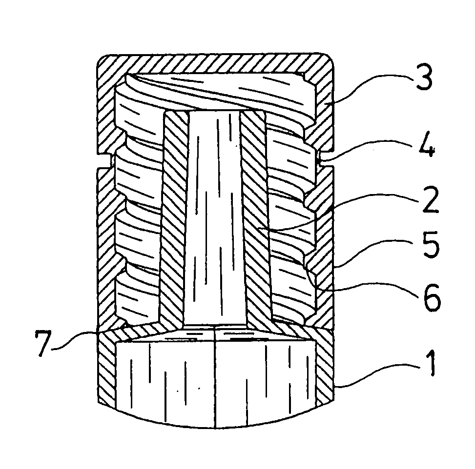
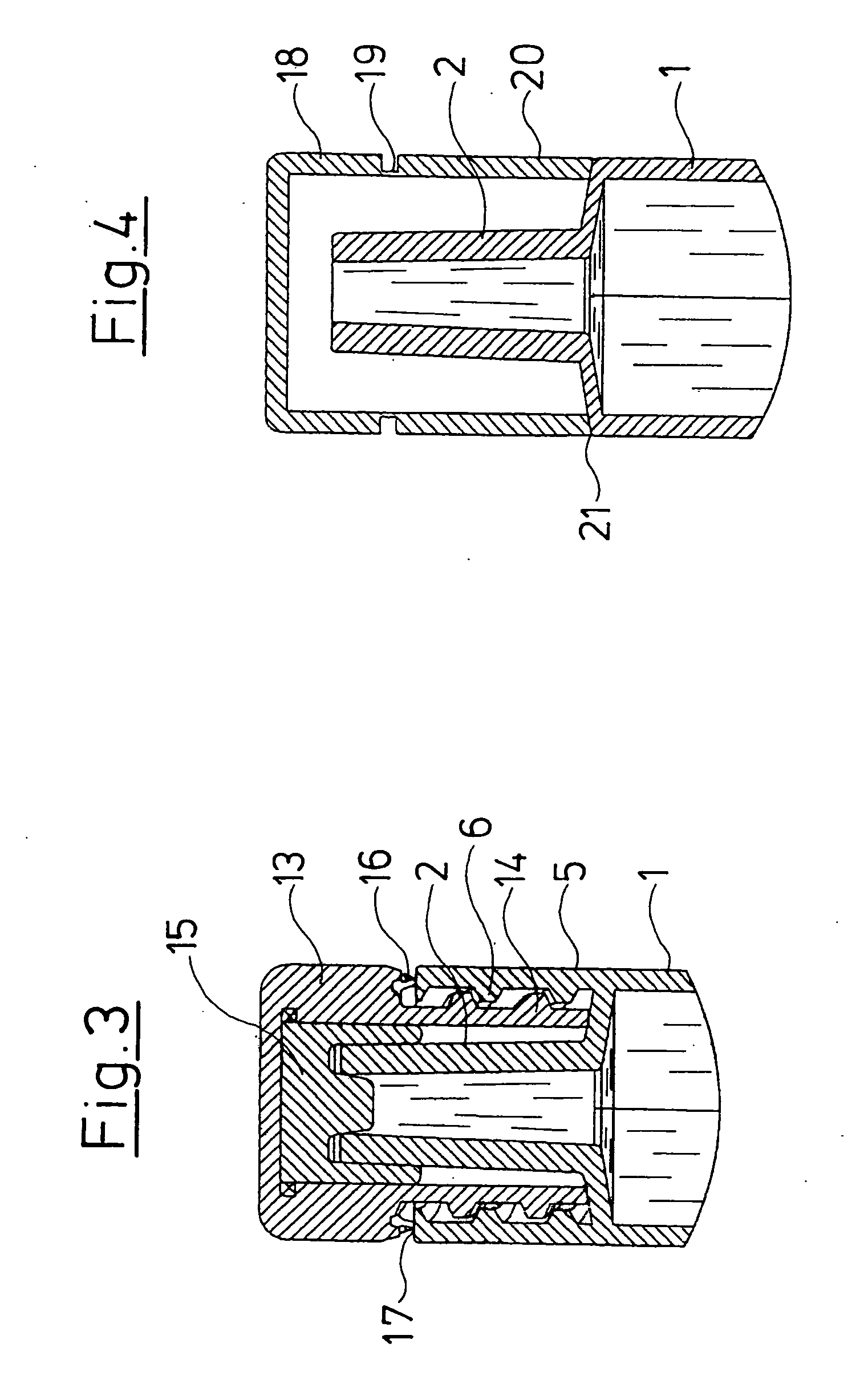
[0025] In FIG. 1 there is shown the connection end of a syringe cylinder, which opens into a Luer connection 2 which in a manner known per se is provided for placing on a cannula. The Luer connection 2 and the syringe cylinder 1 are formed as one piece as a plastic injection molded part.

[0026] A cap 3 covering the Luer connection 2 at the free end is provided as a tamper-evident closure, which via a circumferential frangible web 4 is connected to a cylinder section 5 which on its inner side comprises a thread 6 and surrounding the Luer connection 2 connects to the connection-side end of the syringe cylinder 1. The cap 3, the frangible web 4 and the cylinder section 5 are likewise formed as one piece as a plastic injection molded part. The cylinder section 5 at its end face facing the syringe cylinder 1 is firmly connected to this cylinder with a material fit by ultrasonic welding to form a weld seam 7.

[0027] The tamper-evident closure which is formed in this manner is provided a syr...


PUM


Abstract

The tamper-evident closure is provided for a syringe with a Luer connection or a Luer lock connection, wherein at least the connection end consists of plastic. A cap which is connected to the syringe via at least one frangible web. The cap and the frangible web together with a fixation component are formed as one piece as a plastic injection molded part and are connected to the connection end of the syringe by way of welding.

Description

[0001] 1. Field of the Invention[0002] The invention relates to a tamper-evident closure for a syringe having a plastic connection end with a Luer connection and a cap and a frangible web formed as a single injection molded part, wherein the cap is fitted to the Luer connection.[0003] 2. Description of the Related Art[0004] With syringes, in particular prefilled syringes, one provides a tamper-evident closure which ensures the integrity for the user, i.e. the integrity of the closure and thus of the medium filled into the syringe. Such tamper-evident closures are counted as belong to the state of the art and are known for example from U.S. Pat. No. 5,135,496. This document discloses a glass cylinder on whose end there is attached a component consisting of plastic which comprises a Luer connection onto which later the cannula is placed in a manner known per se, or via which the syringe is connected in another manner. This Luer connection is sealingly closed with a plug which complete...

Claims


Application Information

Patent Timeline
Patent Type & Authority Applications(United States)
IPC IPC(8): A61M5/32A61M5/31A61M5/50
CPCA61M5/5086A61M2005/312A61M2005/3104
Inventor HEINZ, JOCHENROLLE, ALEXANDERSCHILLING, DIETER
Owner TRANSCOJECT
Why Eureka
Try Eureka