Method of jetting viscous medium

Inactive Publication Date: 2004-06-24
MYDATA AUTOMATION
View PDF5 Cites 18 Cited by
  • Summary
  • Abstract
  • Description
  • Claims
  • Application Information

AI Technical Summary

Problems solved by technology

Also, there is the possibility that after the mounting of the assembly in the jetting apparatus, the alignment of said assembly deviates from the one intended.
Furthermore, for the preferred embodiments where the Z-position of the nozzle is calculated through position measurements of viscous medium deposits, if some portion of the assembly is at a lower position than the nozzle exit hole, then the height determined from the calibration described above does not reveal the whole truth about how low

Method used


Image

  • Method of jetting viscous medium
  • Method of jetting viscous medium
  • Method of jetting viscous medium

Examples


Embodiment Construction

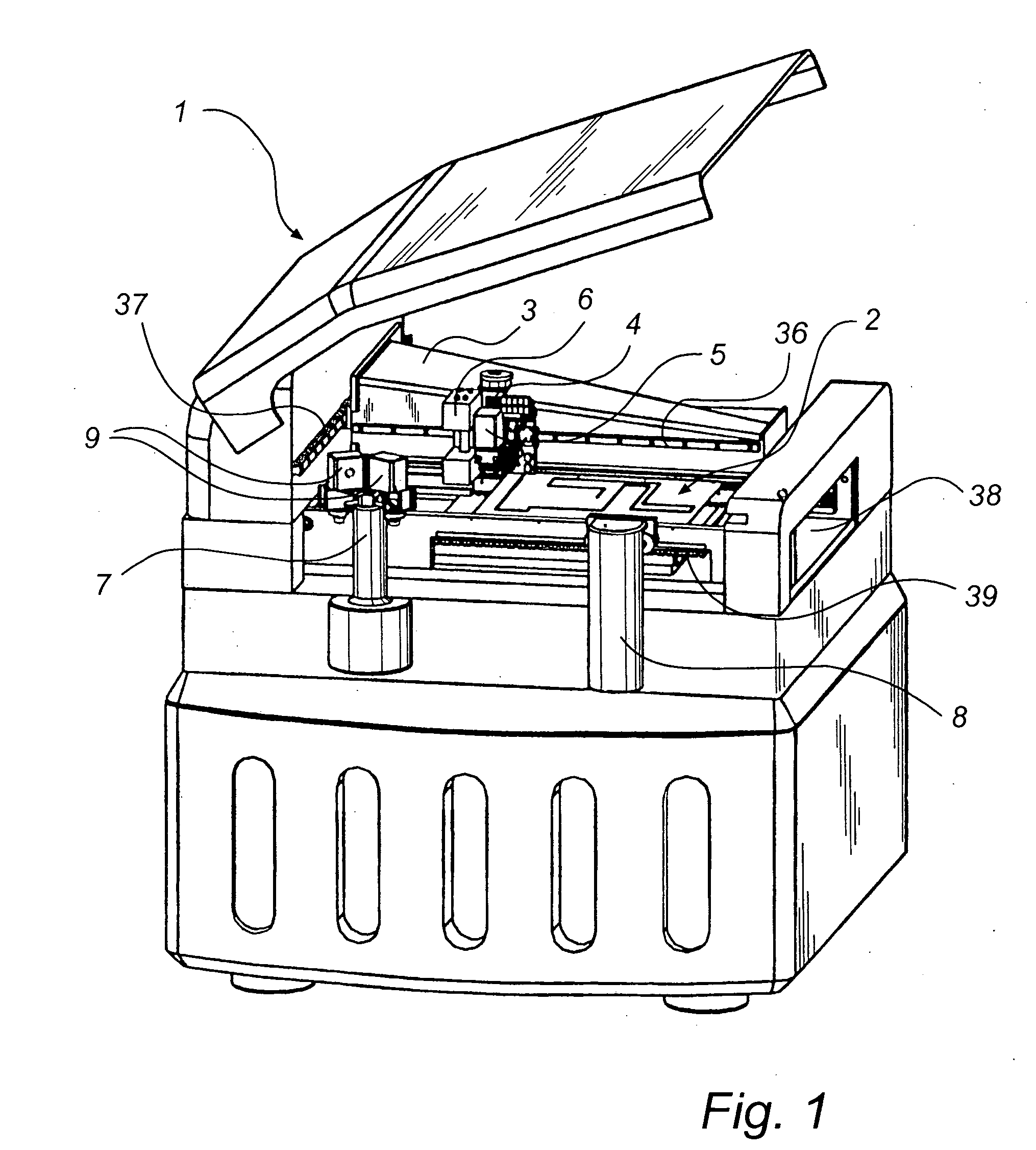
[0059] With reference to the accompanying figures, there will now be described an embodiment of the inventive method of the present invention. First, a jetting assembly and an apparatus for jetting for which the assembly is intended are described with reference to FIG. 1.

[0060] FIG. 1 illustrates a presently preferred embodiment of a machine 1 for providing a substrate 2 with deposits by jetting droplets of a viscous medium onto the substrate 2, in accordance with the present invention. Let us for simplicity assume that the viscous medium is solder paste, which is one alternative as defined above. In this embodiment the machine 1 is of a type comprising an X-beam 3 and an X-wagon 4 connected with the X-beam 3 via an X-rail 36 and reciprocatingly movable along the X-rail 36. The X-beam, in turn, is reciprocatingly movably connected with a Y-rail 37, thereby being movable perpendicularly to the X-rail 36. The Y-rail 37 is rigidly mounted in the machine 1. Generally, the movements are ...


PUM


Abstract

The invention relates to a method of improving the performance of a jetting assembly in an apparatus for jetting droplets of viscous medium on the fly onto a substrate. The jetting assembly is releasably mounted in the apparatus and comprises a nozzle, an ejection mechanism connected to the nozzle, and a viscous medium container connect to the eject mechanism. Information relating to an XY-position and a Z-position is obtained together with information regarding the exit velocity a droplet of viscous medium has when it exits the nozzle. The information is used as a basis for adjusting a trigger position of the nozzle for the subsequent jetting of droplets. The invention also concerns such a jetting assembly comprising storage means arranged to receive and hold calibration information of properties of the assembly obtained during calibration measurements.

Description

[0001] The present invention relates to the field of jetting viscous medium onto substrates. More particularly, the invention relates to a method of improving the performance of a jetting assembly in an apparatus for jetting droplets of viscous medium onto a substrate.TECHNICAL BACKGROUND[0002] Within the field of jetting droplets of viscous medium onto a substrate, particularly solder paste onto an electronic circuit board, there is an increased desire to perform the actual jetting "on the fly", i.e. with relative movement between the substrate and the jetting device during jetting and without stopping for each location on the substrate where viscous medium is to be deposited, in order to increase the manufacturing speed of electronic circuit boards.[0003] A further means for improving the manufacturing speed of electronic circuit boards is to provide reduced idle time of the manufacturing line. One way of doing this is disclosed in the co-pending International patent application p...

Claims


Application Information

Patent Timeline
IPC IPC(8): B41J2/01B05D1/26B05D3/00B23K3/06H05K3/34H05K13/04
CPCH05K13/0469B23K3/0607
Inventor HOLM, WILLIAMKAMFORS, MIKAELFRIDSELL, MAGNUS
Owner MYDATA AUTOMATION
Why Eureka
Try Eureka