Surface-mount type antenna and antenna apparatus

a technology of antenna apparatus and antenna, which is applied in the direction of resonant antennas, substantially flat resonant elements, elongated active element feed, etc., can solve the problems of difficult resonant frequency adjustment operation, inability to achieve desired antenna characteristics as designed with stability, and difficulty in fine adjustment of resonant frequency

Inactive Publication Date: 2004-07-01
KYOCERA CORP
View PDF8 Cites 38 Cited by
  • Summary
  • Abstract
  • Description
  • Claims
  • Application Information

AI Technical Summary

Problems solved by technology

In this case, however, the variation of the resonant frequency corresponding to the cut length is so significant that the resonant-frequency adjustment operation becomes difficult.
As a result, the desired antenna characteristics as designed cannot be readily attained with stability.
This is disadvantageous in terms of fine adjustment of the resonant frequency that is important to achieve satisfactory antenna characteristics.
Due to the influence of the variation of the resonant frequency, the amount of variation in the resonant f

Method used


Image

  • Surface-mount type antenna and antenna apparatus
  • Surface-mount type antenna and antenna apparatus
  • Surface-mount type antenna and antenna apparatus

Examples


Embodiment Construction

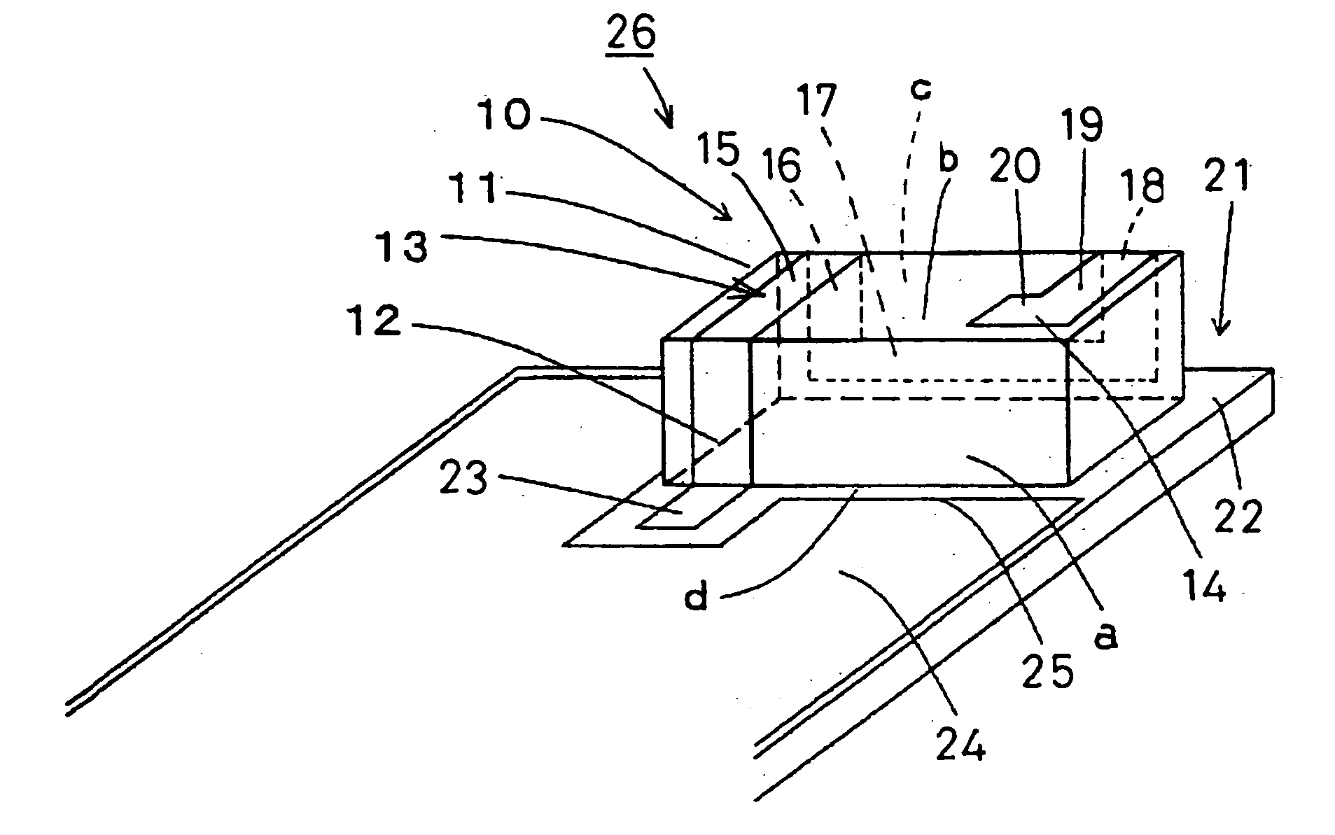
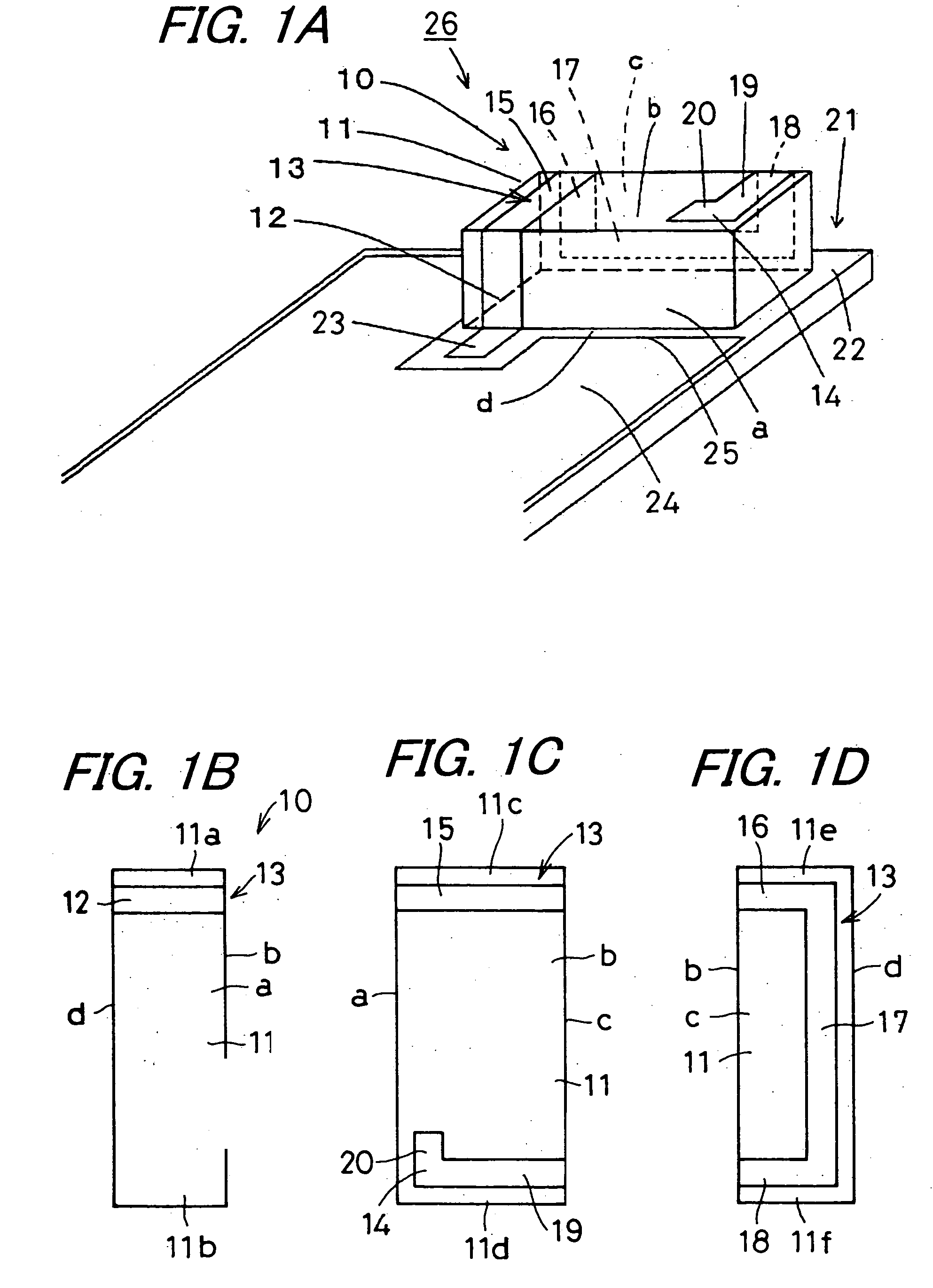
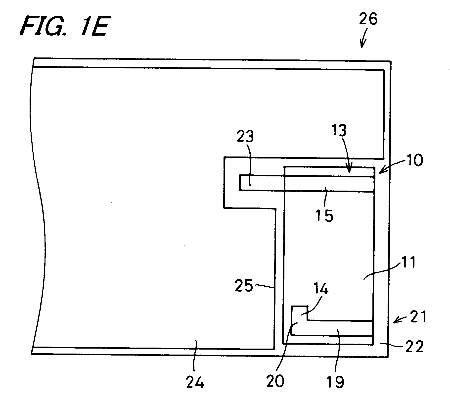
[0140] Next, a description will be given below as to practical examples of the surface-mount type antenna and the antenna apparatus embodying the invention.

[0141] There were built a prototype of the first surface-mount type antenna 10, 30 and 50 of the invention shown in FIGS. 1A to 1E, 2A to 2E and 3A to 3E and also, for comparison purposes, a prototype of the conventional surface-mount type antenna 200 shown in FIG. 10. Firstly, an alumina-made base body (dimension: 10 mm.times.4 mm.times.3 mm) is prepared. Then, 1 mm-wide conductor patterns of different configurations are formed, using silver conductors, to realize four pieces of radiating electrodes respectively shown in FIGS. 1A to 1E, 2A to 2E, 3A to 3E and 10. Each of the radiating electrodes is formed on the base body. As the mounting substrate 21, 41, 62 and 210, a 0.8 mm-thick glass epoxy substrate is used. The ground conductor layer 24, 44, 65 and 209 is 40 mm in breadth and 80 mm in length. That part of the ground conduc...


PUM


Abstract

An surface-mount type antenna includes a rectangular parallelepiped base body, a feeding terminal formed at one-end-side part of one side surface thereof, and a radiating electrode, to one end of which is connected the feeding terminal, disposed such that its other end is routed from one-end-side part of one side surface, through one-end-side part of one principal surface, to another-end-side part of one principal surface, and extends from the other-end-side part to the one end side part parallelly with a ridge of the base body, and is eventually formed into an open end. An antenna apparatus is constructed by mounting the surface-mount type antenna on a mounting substrate having a feeding electrode and a ground conductor layer with a linear side edge located near the feeding electrode, with the ridge of the base body arranged parallel to the linear side edge of the ground conductor layer.

Description

[0001] 1. Field of the Invention[0002] The present invention relates to a surface-mount type antenna which is a compact antenna, and an antenna apparatus for use in mobile communication apparatus such as a cellular phone.[0003] 2. Description of the Related Art[0004] Recently, in keeping with rapid advancement of down-sized, lightweight, and high-performance mobile communication equipment such as a cellular phone, miniaturization and high performance have come to be increasingly demanded of an antenna which constitutes such equipment. To meet such demands, for example, a surface-mount type antenna has hitherto been developed.[0005] Now, a surface-mount type antenna of conventional design and an antenna apparatus incorporating the antenna will be described with reference to a perspective view shown in FIG. 10.[0006] In FIG. 10, reference numeral 200 represents a surface-mount type antenna. The surface-mount type antenna 200 is mounted on a mounting substrate 210, thus constituting an...

Claims


Application Information

Patent Timeline
IPC IPC(8): H01Q1/12H01Q1/38H01Q1/22H01Q1/24H01Q9/04H01Q9/42
CPCH01Q1/12H01Q1/22H01Q9/0457H01Q9/0407H01Q1/2283H01Q1/24
Inventor IKUTA, TAKANORISATO, AKINORIWATADA, KAZUOMURAKAWA, SHUNICHI
Owner KYOCERA CORP
Why Eureka
Try Eureka