Push-button switch member and manufacturing method of same

a technology of push-button switch and manufacturing method, which is applied in the direction of emergency contacts, contact mechanisms, emergency connections, etc., can solve the problems of inability to ensure sufficient light amount, difficult design of push-button switches, and inability to meet the requirements of us

Inactive Publication Date: 2004-07-08
SHIN-ETSU POLYMER CO LTD
View PDF5 Cites 31 Cited by
  • Summary
  • Abstract
  • Description
  • Claims
  • Application Information

AI Technical Summary

Problems solved by technology

In such case, a design of a push-button switch is made difficult because of increased number of parts or elements to be arranged, and in an adverse case, nevertheless, sufficient light amount cannot be ensured for recognizing the displayed contents on the display sections 34 in dark place, thus being not so practical.
However, in the conventional method mentioned above, mere portion of the light generated from the light source can be contributed to visually recognize the display section 34, and even in a large power consumption, the ability of the visual recognition could not be improved, thus being conflictive
In addition, it is difficult to make the thickness of the push-button switch 30 thinner because the light sources 35, 36, 38 and the light guide members 37 are disposed between the key top portions 31 and the contact portions 39 arranged on the circuit board 33 opposing to the key top portions 31, which results in restriction for making the thickness of the input device or machinery body thinner, as well as results in increase in weight.
However, in the method in which the transparent conductive layer is formed with the ceramic layer by utilizing the ion spattering method using tin oxide or like, the ceramic layer is itself brittle and is not almost extendable, so that even if a transparent insulating film is elongated so as to have a desired key top shape, the transparent conductive layer does not follow such shape and a resistance rapidly increases, thus being inconvenient.
However, in this method, the resistance is not reduced so remarkably even with much amount of ceramic powder content, and it is difficult to uniformly disperse the ceramic powder.
Accordingly, at a time when it is desired to elongate to deform the transparent insulating film as a base material so as to provide a desired shape, the linkage of the ceramic powder of the transparent conductive layer is easily destroyed, resulting in increasing of resistance and, hence, causing of uneven luminance.

Method used


Image

  • Push-button switch member and manufacturing method of same
  • Push-button switch member and manufacturing method of same
  • Push-button switch member and manufacturing method of same

Examples


first embodiment

[0072] [First Embodiment of the Invention]

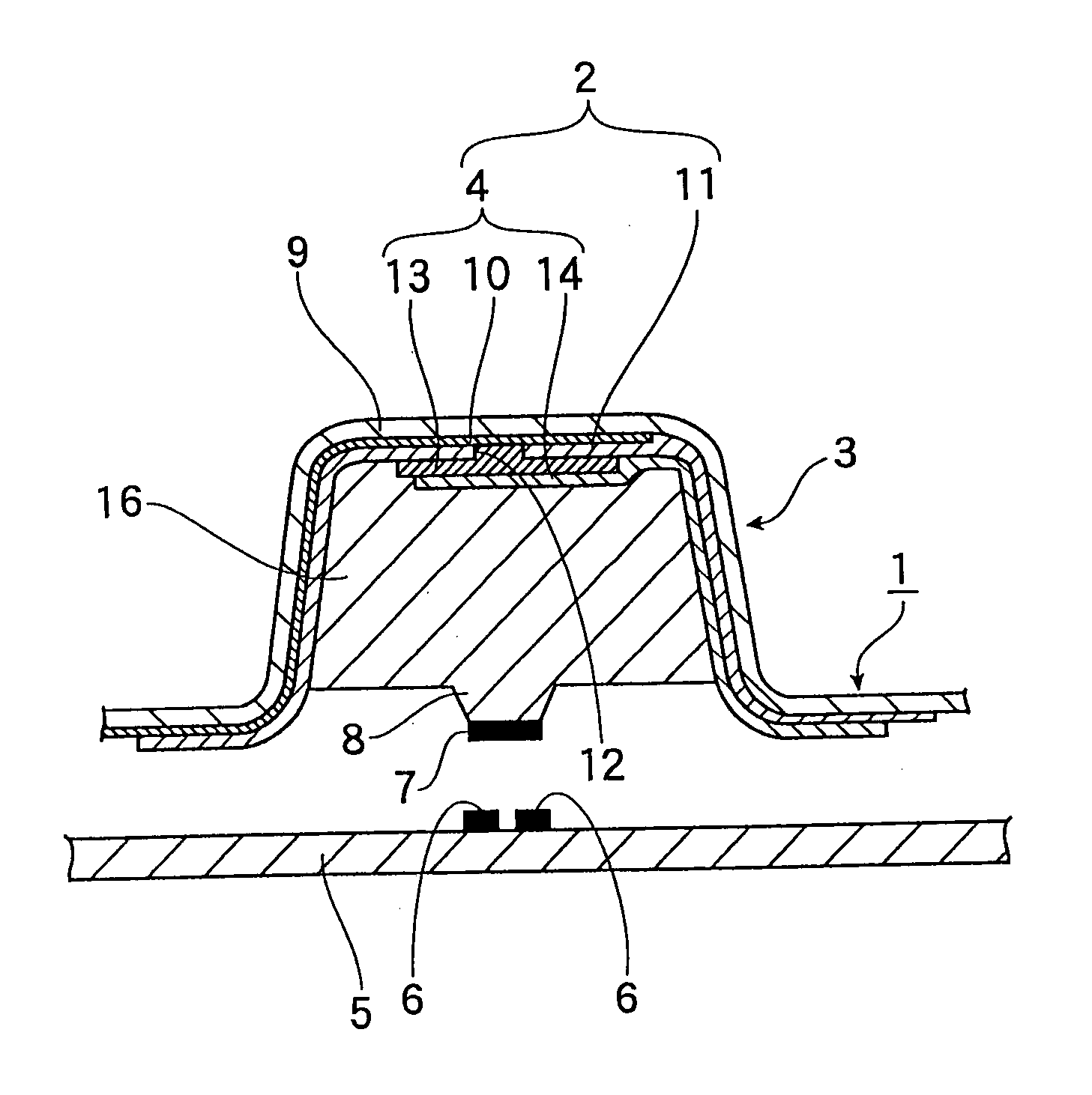
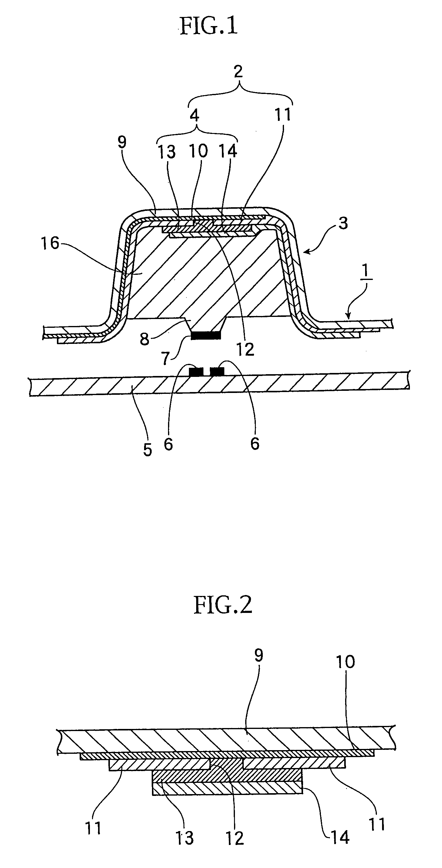
[0073] FIG. 1 is a sectional view showing an essential portion of a member for a push-button switch according to a first embodiment of the present invention.

[0074] A member 1 for constituting or forming a push-button switch (called hereinlater "push-button switch member") according to the first embodiment shown in FIG. 1 is provided with a key-top portion 3 and a display section 2 displayed with switching functions by means of letters, symbols, figures or like, the display section 2 being provided on a top (front) surface side of the key-top portion 3 and utilizing an area (plane or flat) emitter 4 spontaneously emitting a light.

[0075] The push-button switch member 1 according to the first embodiment is provided with a movable contact point 7 disposed so as to oppose to a stationary contact point 6 formed on a circuit board 5. More in detail, the movable contact point 7 is formed to a front end of a push projection 8 formed to a central port...

second embodiment

[0132] [Second Embodiment of the Invention]

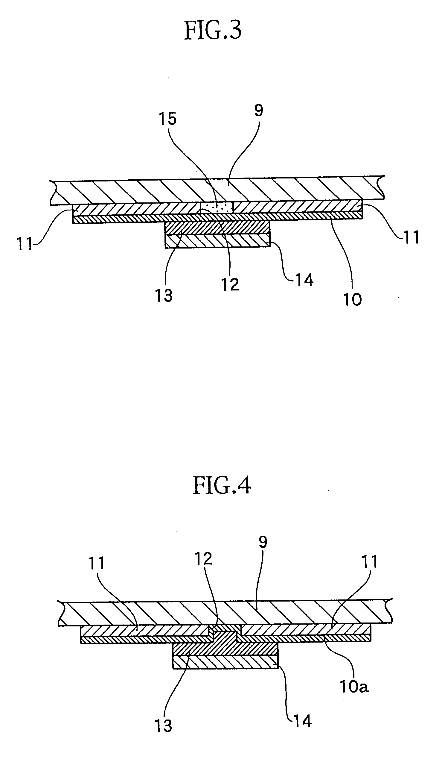
[0133] The push-button switch member of this embodiment has substantially the same structure as that of the first embodiment except that a conductive member connected to the transparent electrode and the base electrode is located. A structure near the top surface portion of the key-top portion according to this embodiment will be explained hereunder with reference to FIG. 12 which substantially corresponds to the details of FIG. 3.

[0134] The opaque color layer 11 as a shielding layer and the transparent color layer 15 as the display section 2 are disposed below the transparent insulating film 9. An anchor coat layer 17 is formed under the transparent insulating layer 15 to enhance adhesion performance of the transparent electrode 10. This anchor coat layer 17 may be eliminated if the transparent color layer 15 has the same function as that of the anchor coat layer 17. It is not necessary to make the transparent electrode 10 large and, in or...

third embodiment

[0149] [Third Embodiment of the Invention]

[0150] FIG. 17 represents a push-button switch member according to the third embodiment of the present invention.

[0151] The push-button switch member 1 of the third embodiment of the present invention shown in FIG. 17 is provided with the display section 2, displaying letter, symbol or figure, arranged at the intermediate portion of the key-top portion 3 and adopts the area emitter 4 of self-emitting type.

[0152] The push-button switch member 1 according to the third embodiment 3 comprises a contact point sheet 23 and a key-top portion 3 formed integrally therewith. The contact point sheet 23 has an elastically deformable dome portion 22 having an inner surface to which a movable contact point 7 is arranged at a portion corresponding to a stationary contact point 6 formed on the circuit board 5 in positional conformity therewith, and the key-top portion 3 is provided with a push projection 8 formed to the rear surface of the key-top portion 3...


PUM

PropertyMeasurementUnit
light transmittanceaaaaaaaaaa
diameteraaaaaaaaaa
aspect ratioaaaaaaaaaa

Abstract

It is an object to provide a push-button switch member (1), by utilizing light energy with out any loss for back-lightening on a display section, capable of realizing the back-lightening to the display section with even luminance while suppressing power consumption and having high visibility and thin thickness, the push-button switch member comprising a key-top portion (3) and a cover base member provided with the key top portion at a predetermined portion; thereof and adapted to be mounted to the circuit board (5), the key-top portion (3) being provided with a display section (2) displaying a switching function and an area emitter (4) integrally formed with the display section, wherein the area emitter member (4) is provided with a light emitting layer (13) disposed between a base electrode (14), and a transparent electrode (10) disposed so as to oppose to the base electrode (14) and the transparent electrode (10) arranged to be contacted to the display section (2) is formed of a transparent conductive polymer.

Description

[0001] The present invention relates to a member for constituting or forming a push-button switch (called hereinlater "push-button switch member") and a method of manufacturing such push-button switch member, the push-button switch being provided with a display section displaying a switching function in an input device such as cellular phone (portable phone), portable terminal such as PDA (Personal Digital Assistant), car-stereo, board computer mounted to vehicle, audio-set, measurement instrument, personal computer, etc., and more particularly, being applicable to the push-button switch of a back-light type switch capable of lightening up the display section even in a dark place.BACKGROUND TECHNOLOGY[0002] In prior art, for a member for push-button switch utilized for the input device of the kind mentioned above, it is said to be necessary to have a letter back-lightening function for back-lightening a display section showing a push-button switching function in a night use.[0003] F...

Claims


Application Information

Patent Timeline
Patent Type & Authority Applications(United States)
IPC IPC(8): B29C43/18H01H13/02B29C43/20H01H9/18H01H11/00H01H13/14H01H13/70H01H13/702H04M1/02H05B33/28
CPCB29C43/18B29C43/203H01H9/182H01H13/14H01H13/702H01H2001/0005Y10T29/49105H01H2207/00H01H2207/002H01H2219/018H01H2219/03H01H2219/034H05B33/28H01H2009/186H01H13/00
Inventor KAWAGUCHI, TOSHIYUKIHOTTA, SHINJITAKAHASHI, MASAYUKI
Owner SHIN-ETSU POLYMER CO LTD
Why Eureka
Try Eureka