System apparatus and method for diagnosing a flow system

a flow system and system technology, applied in the field of system apparatus and method for diagnosing a flow system, can solve the problems of difficult, reliably and quickly, difficult to find the root cause of alarms, and often dramatic changes in state, so as to achieve correct and quick measures

Inactive Publication Date: 2004-07-08
GOALART
View PDF7 Cites 36 Cited by
  • Summary
  • Abstract
  • Description
  • Claims
  • Application Information

AI Technical Summary

Benefits of technology

[0005] Therefore, an object of the invention is to offer a new functionality for control systems, which will help the operators to analyze and understand situations in the industrial process, and thereby to take correct and quick measures. Thus, to offer an increased understanding of the process in critical situations when the operators are overloaded with a large amount of system information such as alarms, and thereby helping the operators of taking optimal countermeasures.
[0006] Another object of the present invention is to provide a system, an apparatus, a method and a computer program product that facilitate the monitoring and the diagnosis of an industrial process using a minimum of computational resources.
[0012] A fault diagnozer can further be comprised in the present invention, which fault diagnozer is arranged to find the root causes for unfulfilled goals or purposes of the flow system by reducing the functional model to be traversed during the fault diagnosis. By finding the root causes, countermeasures can be taken more efficiently and correctly.

Problems solved by technology

In critical situations the operators of complex industrial processes are often overloaded by a large amount of system information, e.g., a plurality of alarms.
Even in moderately complex systems it can be quite difficult to, reliably and quickly, find the root causes of the alarms, i.e. the locations of the faults.
However, during normal operation, the operators are usually more or less redundant, while in fault or alarm situations they suddenly have to override the computerized control system and manually control the system.
This change of state is often dramatic, since the operators are confronted with an unknown situation where plant state information is diffuse and the control monitors are flooded with alarms.
Today's control systems offer very little help in such situations and there is a great risk for misunderstanding the new situation and consequently for taking sub-optimal or even wrong control measures.
However, this method and apparatus is limited to only one kind of fault diagnosis, namely to find the cause to a detected plant anomaly.
Thus, it does not provide support to the operators in other tasks, such as detecting sensor faults, finding root causes in complex fault situations, predicting system behavior, and planning control actions.
Thus, the method for finding the cause to a detected plant anomaly according to U.S. Pat. No. 5,914,875 is unnecessary computationally inefficient.

Method used


Image

  • System apparatus and method for diagnosing a flow system
  • System apparatus and method for diagnosing a flow system
  • System apparatus and method for diagnosing a flow system

Examples


Embodiment Construction

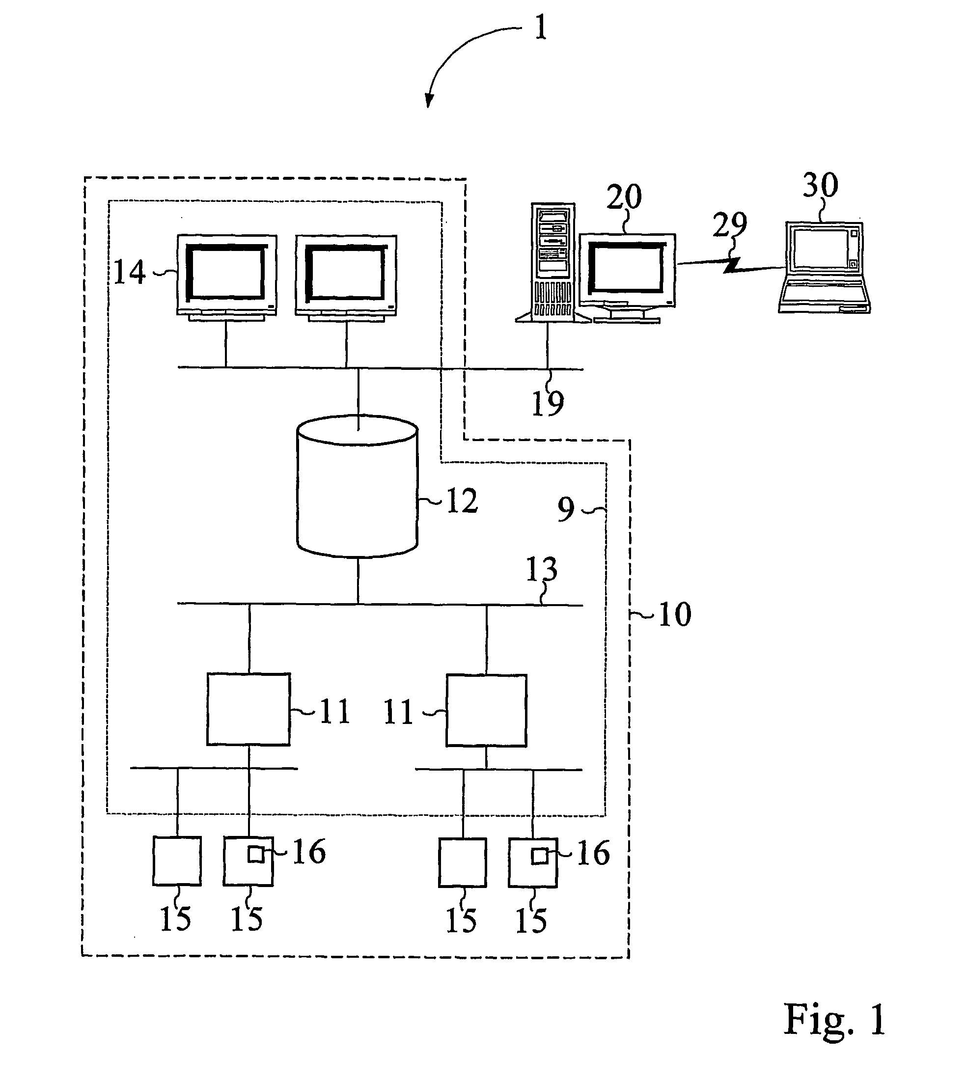
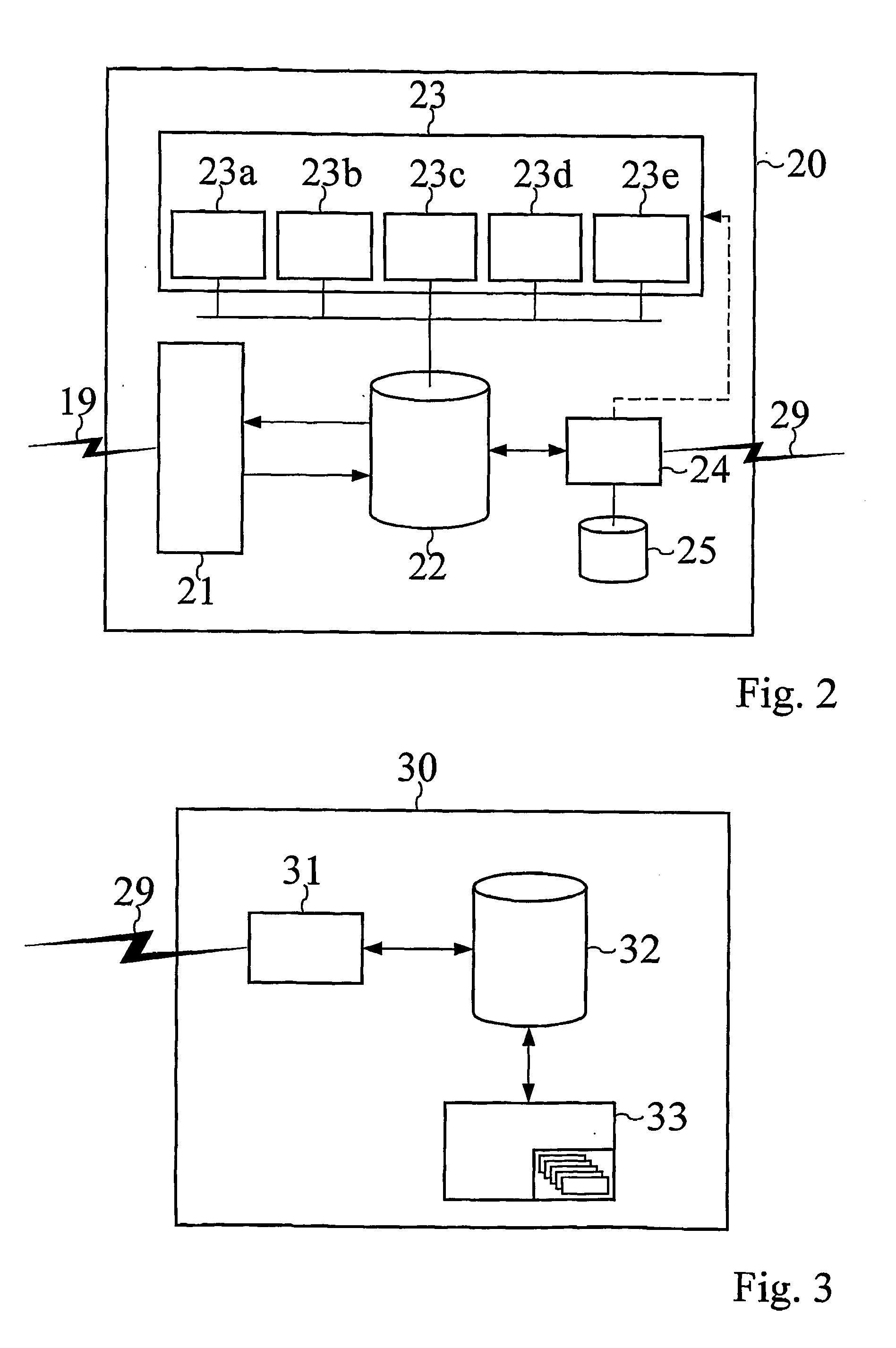
[0190] To illustrate an example of how the service functions 23 work together as a system, the engine system in FIG. 17 will be used. The diagnostic apparatus 20 is connected to the target system 10, which in this case is the engine.

[0191] The system detects that the goal "cool engine" is not fulfilled, i.e., the temperature of the engine is too high, and the diagnostic system manager 24 orders the fault diagnozer 23c to execute its operation. The fault diagnozer 23c finds from the sensor readings that the "lubricant source" (F8) has a low capacity alarm, the "lubricant transport" (F9) has a low flow alarm, the "water pump" (F1) has a low temperature alarm, and the "engine heat exchanger" (F2) has a high temperature alarm, thus the result of the fault diagnosis is that the "cool engine"-goal has failed due to failure of the lubricant supply system.

[0192] The diagnostic system manager 24 next orders the sensor fault detector 23b to execute its operation. The sensor fault detector 23b...


PUM


Abstract

The present invention deals with diagnosing of a flow system, using status signals carrying information about said flow system, whereby new status information is generated, which relates to a plurality of aspects of the flow system based on said status signals and dependent on a functional model and on a set of predetermined rules. The invention comprises a diagnostic apparatus (20) arranged to analyze the status signals for example by means of an alarm analyzer (23a) arranged to separate alarms into primary and secondary alarms, a sensor fault detector (23b) arranged to detect sensor values that probably are wrong or a fault diagnozer (23c) arranged to find the root causes for unfulfilled goals. Further the invention can comprise a failure mode analyzer (23d) arranged to detect functions that can stop working in the future or a process measurement analyzer (23e) arranged to analyze the status signals of a specific process.

Description

[0001] The present invention refers to diagnosis of a flow system, and especially to a system, an apparatus, a method and a computer program product for diagnosing the flow system.[0002] In critical situations the operators of complex industrial processes are often overloaded by a large amount of system information, e.g., a plurality of alarms. For example the alarms are caused by faults in different components usually monitored by sensors. Even in moderately complex systems it can be quite difficult to, reliably and quickly, find the root causes of the alarms, i.e. the locations of the faults. Thus today's complex industrial systems can be operated only thanks to advanced computer control systems. However, during normal operation, the operators are usually more or less redundant, while in fault or alarm situations they suddenly have to override the computerized control system and manually control the system. This change of state is often dramatic, since the operators are confronted...

Claims


Application Information

Patent Timeline
Patent Type & Authority Applications(United States)
IPC IPC(8): G05B9/02G06F3/048G05B23/02
CPCG05B9/02G05B23/0278G05B23/0248
Inventor LARSSON, JAN ERICDAHLSTRAND, FREDRIKOHMAN, BENGTTUSZYNSKI, JAN
Owner GOALART
Why Eureka
Try Eureka