Detecting device capable of measuring speed and torque simultaneously

a detection device and speed technology, applied in the direction of linear/angular speed measurement, devices using electric/magnetic means, instruments, etc., can solve the problems of only controlling tension through rotational speed, difficult to maintain a constant speed and torque transmission of rotational mechanism, and difficult to measure torque while shaft rotating, etc., to achieve low noise, low overall dynamic loss, and easy detection

Inactive Publication Date: 2000-10-31
CHANG HSIN ZONG
View PDF0 Cites 34 Cited by
  • Summary
  • Abstract
  • Description
  • Claims
  • Application Information

AI Technical Summary

Benefits of technology

It is the objective of this invention to provide a detecting device that is capable of measuring the rotational speed as well as the torque during the operation and overall dynamic loss is low and the noise is less.
In order to achieve the objective set forth, a detecting device capable of measuring the rotational speed and torque simultaneously is provided. The detecting device comprises a main disk, a pair of sub-detecting disks, a spring socket, a spring member, a sensor, and a display. The main disk has a given thickness and is provided with a shaft hole centrally. The main disk is further provided with a circular recess around the shaft hole. The circular recess is further extended with a plurality of lobe grooves from the peripheral of the circular recess. Each of the lobe grooves is further provided with an adjusting groove in which an adjusting bolt is moveably disposed therein. Then the outer sub-detecting plate of the sub-detecting plate is fixedly attached to the main disk and an output end is formed accordingly. The other detecting is fixedly attached to a spring socket that is provided with a shaft hole at the center. The spring socket includes a plurality of elongate grooves that are equiangularly arranged. The spring socket is also provided with a shaft hole. Each of the elongate grooves is mounted with a spring member therein and part of the spring member extends beyond the spring socket. The other end of the spring member extends beyond the spring socket. The spring socket and the spring member are jointly disposed within the circular recess of the main disk in a manner such that the projected spring is biased against to the adjusting bolt within the adjusting groove. An input end is formed accordingly. Then a shaft is inserted to assemble those elements and that serves the power input. After those elements are assembled by means of a shaft, the spring member may serve as a medium for force transmission. The sensor is disposed above the top surface of those inner and outer sub-detecting disks. The sensor is electrically connected with the display. When the external force is introduced through the shaft, the inner sub-detecting disk is rotated accordingly. The teeth portion of the inner and outer sub-detecting disks are aligned with each other, but not locked up with each other. When the spring member is rotated to a certain angle, an offset difference will be established between the inner and outer sub-detecting disks. When the resilient force resulted from the deformation of the spring member is larger than the load, the input end and the output end will be rotated simultaneously. When the load is released or equal to zero (0), the input end is resumed to the original relative position. The sensor may measure the proportional ratio between no-pass and pass of those two inner and outer sub-detecting disks. Accordingly, the rotational speed and the torque value can be therefore measured. The rotational speed and the torque values can be readily detected in a dynamic, lower power loss, and noiseless manner.
According to one aspect of the present invention, the spring member is inserted into the elongate groove of the spring socket and the upper portion of the spring is inserted into the cutout of the main disk in a manner such that the upper portion of the spring is biased against with the adjusting bolt of the adjusting groove of the main disk. The adjusting bolt can be moved upward and downward along the adjusting groove to adjust the preset torque values. When the detecting device is rotated, the maximum of forward rotating angle of the spring element is about three (3) degrees. When the spring member is moved back, it is stopped by the cutout of the main disk. Even the angular difference between those two inner and outer sub-detecting disks is quite small, this variation between those two sub-detecting disks can be readily measured by the sensor and the measurement will be further transmitted to the display. This measurement can be displaced by a rectangular wave and corresponding values and that can be readily converted into speed value and torque value. That is another feature of the present invention.
According to another aspect of the present invention, the optical wave measured by the sensor will be transmitted to the display for calculating the proportional rate for converting the rectangular wave and values. When those sub-detecting disks are reset, i.e. the torque is zero (0) when there is no load, the ratio between High / Low will be 50%:50%. If an external force is applied to the shaft, i.e. a load or resistance is applied onto the input end, the outer sub-detecting disk and the inner sub-detecting disk are offset from each other again such that the ratio may become 48%:52%. The higher the torque values, the higher the High / Low ratio. From this ratio, the rotational speed and the torque can be quickly and correctly measured. Accordingly, the rotational speed and torque value can be readily measured under a non-direct contact, dynamic situation. This detecting device also features a low cost, low dynamic loss, noiseless, simple configuration and easy assembling.
According to another aspect of the present invention, the rotational speed and torque values can be readily measured from the sum of the non-pass and pass between the inner and outer sub-detecting disks and the proportional difference rate. When the inner and outer sub-detecting disks are rotated simultaneously, the difference between the high potential interval and lower potential interval and measured by said sensor is the angular value of the distortion of said spring member. The torque value can be readily attained by multiplying the angular value with the rating of said spring member, the torque can be readily determined

Problems solved by technology

Accordingly, maintaining a constant speed and torque transmission for the rotational mechanism has become an important issue in this field.
It is difficult to measure the torque while the shaft is rotating.
However, in the prior art, the tension can only be controlled through the rotational speed.
Nevertheless, the overall configuration is bulky and complicated.
The controlling manner is also not smooth.
As a result, there are a lot of limits on the utilization and it can not be upgraded.

Method used


Image

  • Detecting device capable of measuring speed and torque simultaneously
  • Detecting device capable of measuring speed and torque simultaneously
  • Detecting device capable of measuring speed and torque simultaneously

Examples


Embodiment Construction

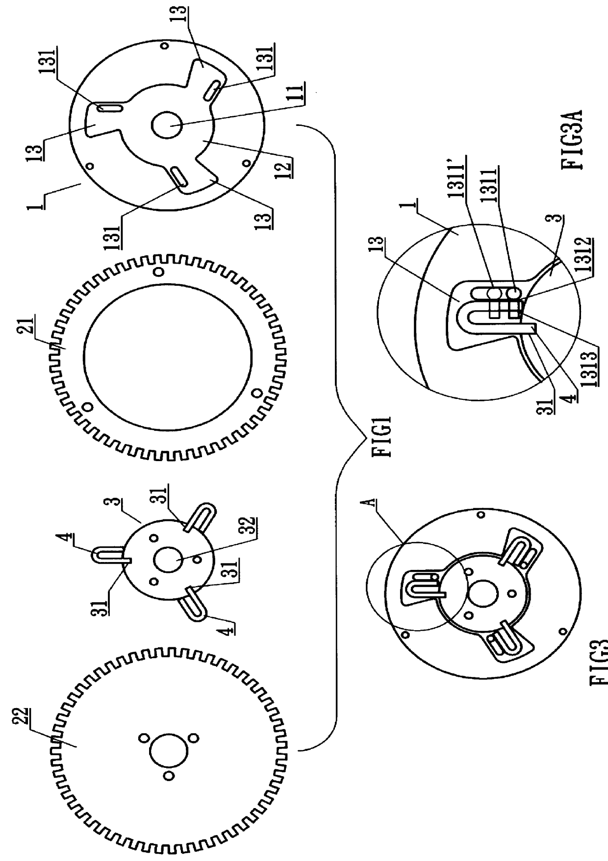
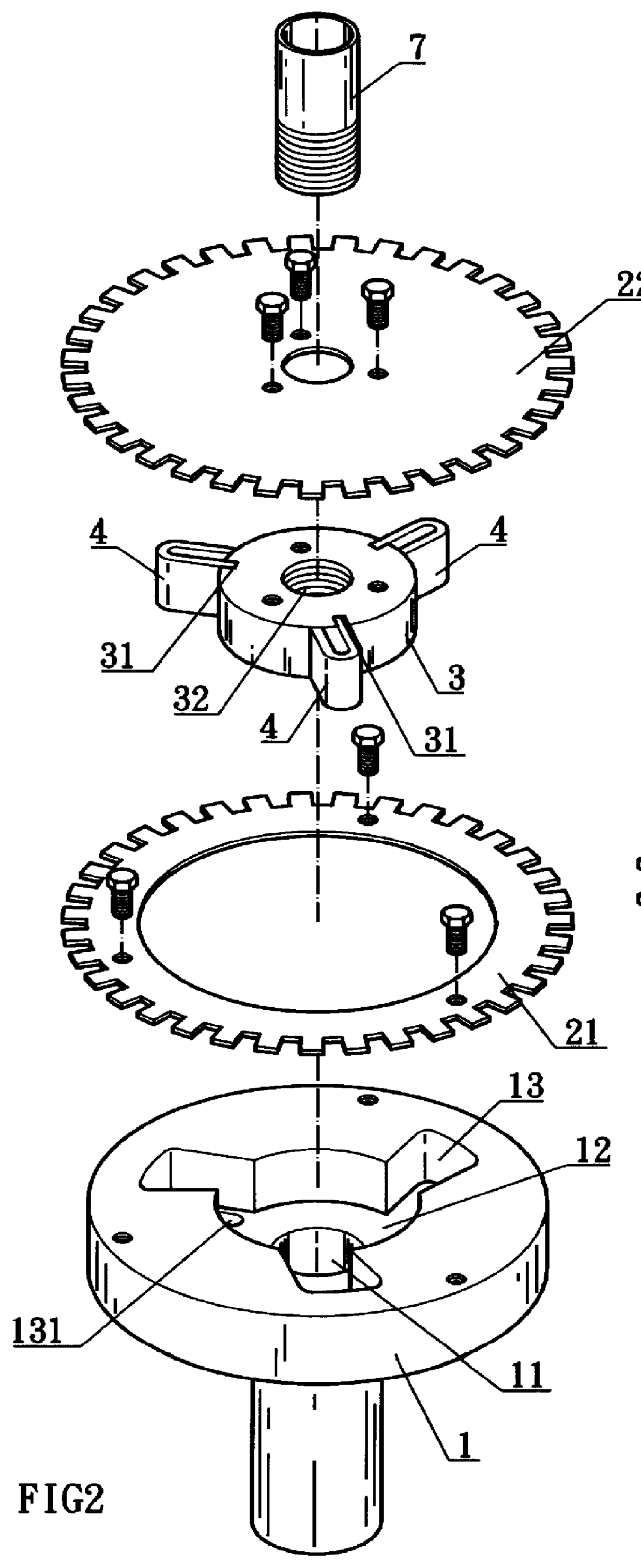
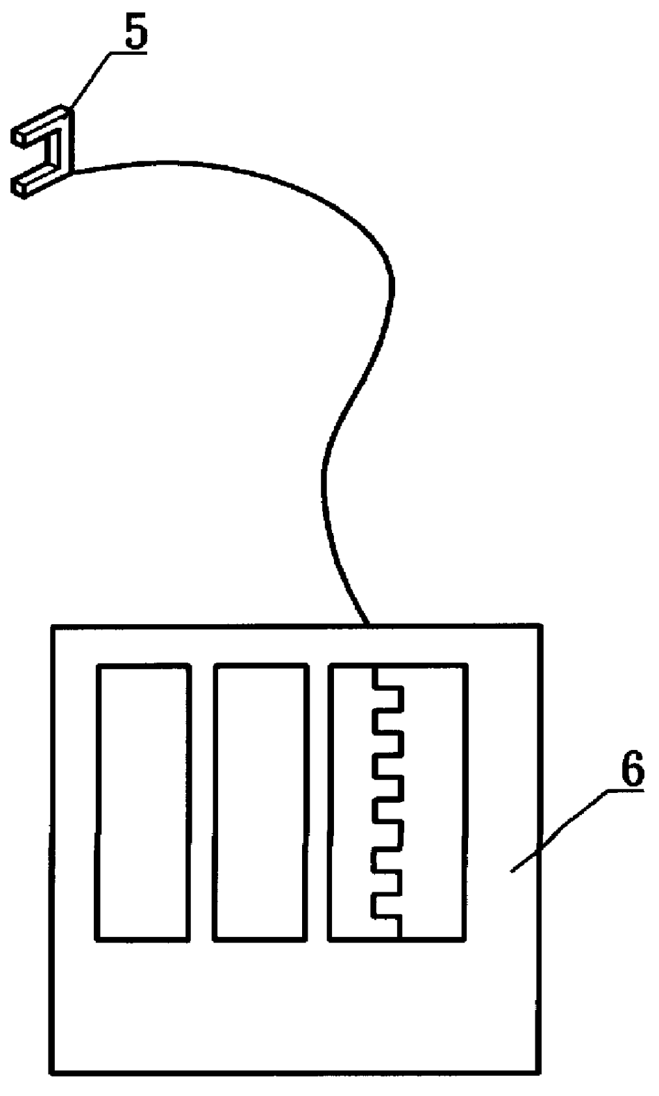
Referring to FIGS. 1 and 2, the detecting device capable of measuring the rotational speed and torque simultaneously comprises a main disk 1, a sub-detecting disk 2, a spring socket 3, a spring member 4, a sensor 5, and a display 6.

The main disk 1 has a given thickness and is provided with a shaft hole 11 centrally. The main disk 1 is further provided with a circular recess 12 around the shaft hole 11. The circular recess 12 is further extended with a plurality of lobe grooves 13 from the periphery of the circular recess 12. In this preferred embodiment, the number of the lobe grooves 13 is three. Each of the lobe grooves 13 is equiangularly arranged. Each of the lobe grooves 13 is further provided with an adjusting groove 131 in which an adjusting bolt 1311 is moveably disposed therein. The adjusting bolt 1311 is fixedly locked onto a limiting tab 1312 that has an opening 1313 for receiving and retaining the spring member 4 thereof. Then the outer detecting plate 21 of the sub-dete...


PUM

PropertyMeasurementUnit
of forward rotating angleaaaaaaaaaa
speedaaaaaaaaaa
torqueaaaaaaaaaa

Abstract

A detecting device is disclosed capable of measuring the rotational speed and torque simultaneously and in which the dynamic loss is reduced to the lowest level. The detecting device has a main disk, a pair of sub-detecting disks, a spring socket, a spring member, a sensor, and a display. The main disk is provided with a shaft hole centrally and with a circular recess around the shaft hole. The circular recess is further extended with a plurality of lobe grooves, each lobe groove having an adjusting groove in which an adjusting bolt is moveably disposed. An outer sub-detecting plate is fixedly attached to the main disk forming an output end, and an inner sub-detecting plate is fixedly attached t a spring socket. Teeth portions of the inner and outer sub-detecting plates are initially aligned with each other, but when the spring member is rotated a certain angle, an offset difference will be established between the inner and outer sub-detecting disks. A sensor measures the proportional ratio between the inner and outer sub-detecting disks. Accordingly, the rotational speed and the torque value can be therefore measured.

Description

FIELD OF THE INVENTIONThe present invention relates to a detecting device, more particularly, to a detecting device capable of measuring the rotational speed and torque simultaneously and wherein the dynamic loss can be reduced to the lowest level. The detecting device capable of measuring the rotational speed and torque simultaneously of the types that comprises a main disk, a pair of sub-detecting disks, a spring socket, a spring member, a sensor, and a display. The main disk has a given thickness and is provided with a shaft hole centrally. The main disk is further provided with a circular recess around the shaft hole. The circular recess is further extended with a plurality of lobe grooves from the periphery of the circular recess. Each of the lobe grooves is further provided with an adjusting groove in which an adjusting bolt is moveably disposed therein. Then the outer sub-detecting plate of the sub-detecting plate is fixedly attached to the main disk and an output end is form...

Claims


Application Information

Patent Timeline
Patent Type & Authority Patents(United States)
IPC IPC(8): G01L3/02G01L3/24G01P3/42G01L3/14G01L3/00G01P3/481
CPCG01L3/1435G01P3/481G01L3/242
Inventor CHANG, HSIN-ZONG
Owner CHANG HSIN ZONG
Why Eureka
Try Eureka