Loading floor for a vehicle and loading apparatus

a technology for loading equipment and vehicles, applied in the field of loading equipment, can solve problems such as the loss of a large amount of loading area

Inactive Publication Date: 2004-08-05
FAURECIA INNENRAUM SYST
View PDF12 Cites 20 Cited by
  • Summary
  • Abstract
  • Description
  • Claims
  • Application Information

AI Technical Summary

Problems solved by technology

However, a common disadvantage of the previously known loading floors and loading apparatuses is that, due to the pull-out mechanism for the loading floor, a considerable amount of loading area is lost.

Method used


Image

  • Loading floor for a vehicle and loading apparatus
  • Loading floor for a vehicle and loading apparatus
  • Loading floor for a vehicle and loading apparatus

Examples


Embodiment Construction

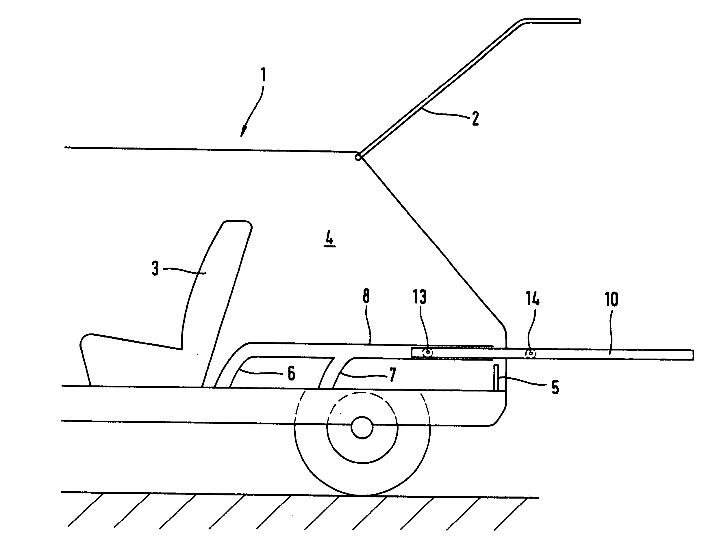
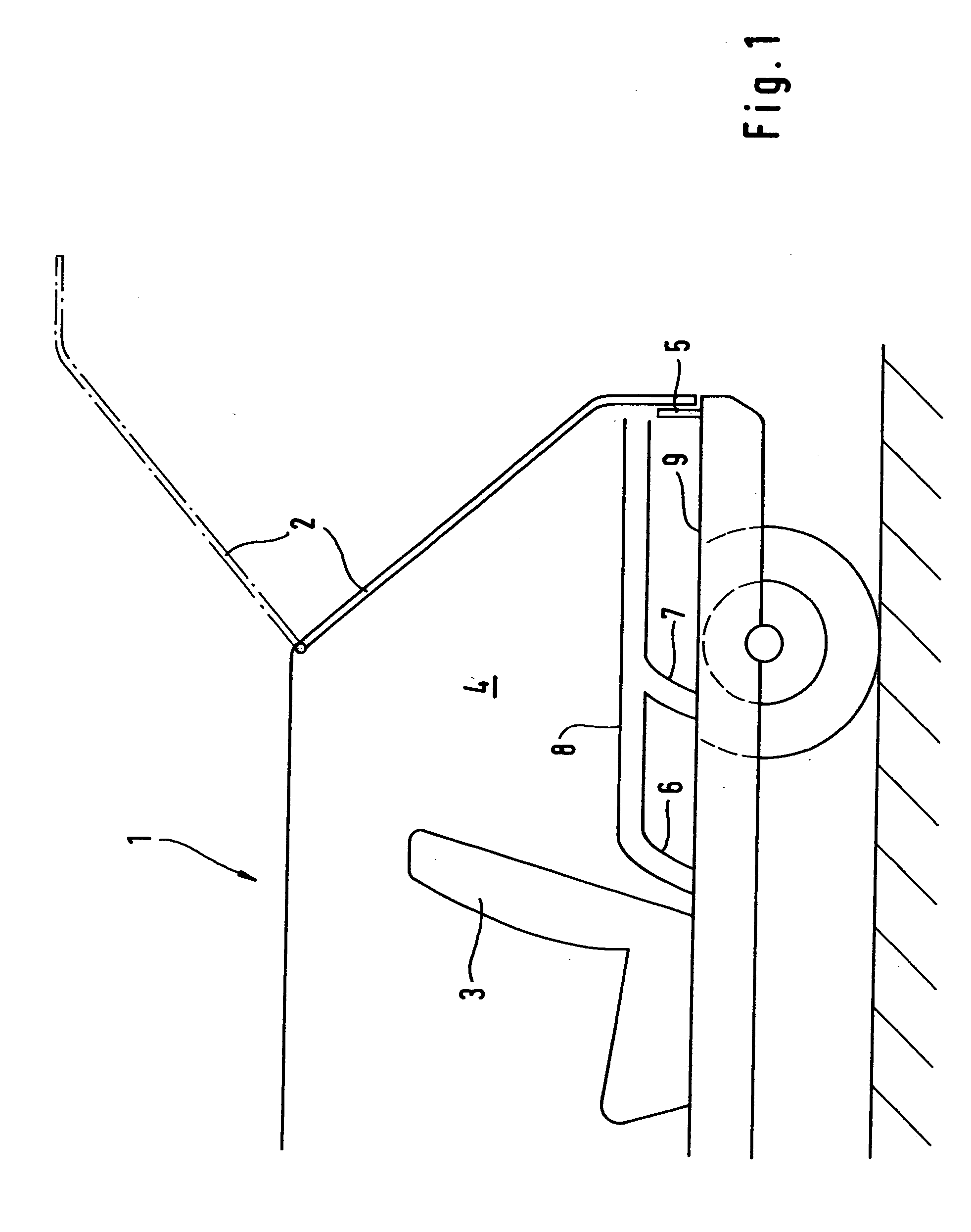
[0036] FIG. 1 shows vehicle 1 with rear hatch 2. Loading area 4 is located behind rear seats 3. Loading area 4 is preferably bordered by loading edge 5 towards the rear. Loading edge 5 has the advantage that it adds to the stability of the body of vehicle 1.

[0037] One guide linkage is provisioned in both side walls of vehicle 1 in the region of loading area 4. The guide linkages consist of curved sections 6 and 7, as well as of straight sections 8. The guide linkage formed by sections 6, 7 and 8 serves to hold corresponding rollers of a loading floor.

[0038] With regard to this, sections 6 and 7 of the guide linkage reach down to, or to just above, vehicle floor 9, so that the loading floor can lay directly on vehicle floor 9. Due to this none of loading area 4 is lost, as compared with a vehicle like vehicle 1 with no retractable / liftable loading floor.

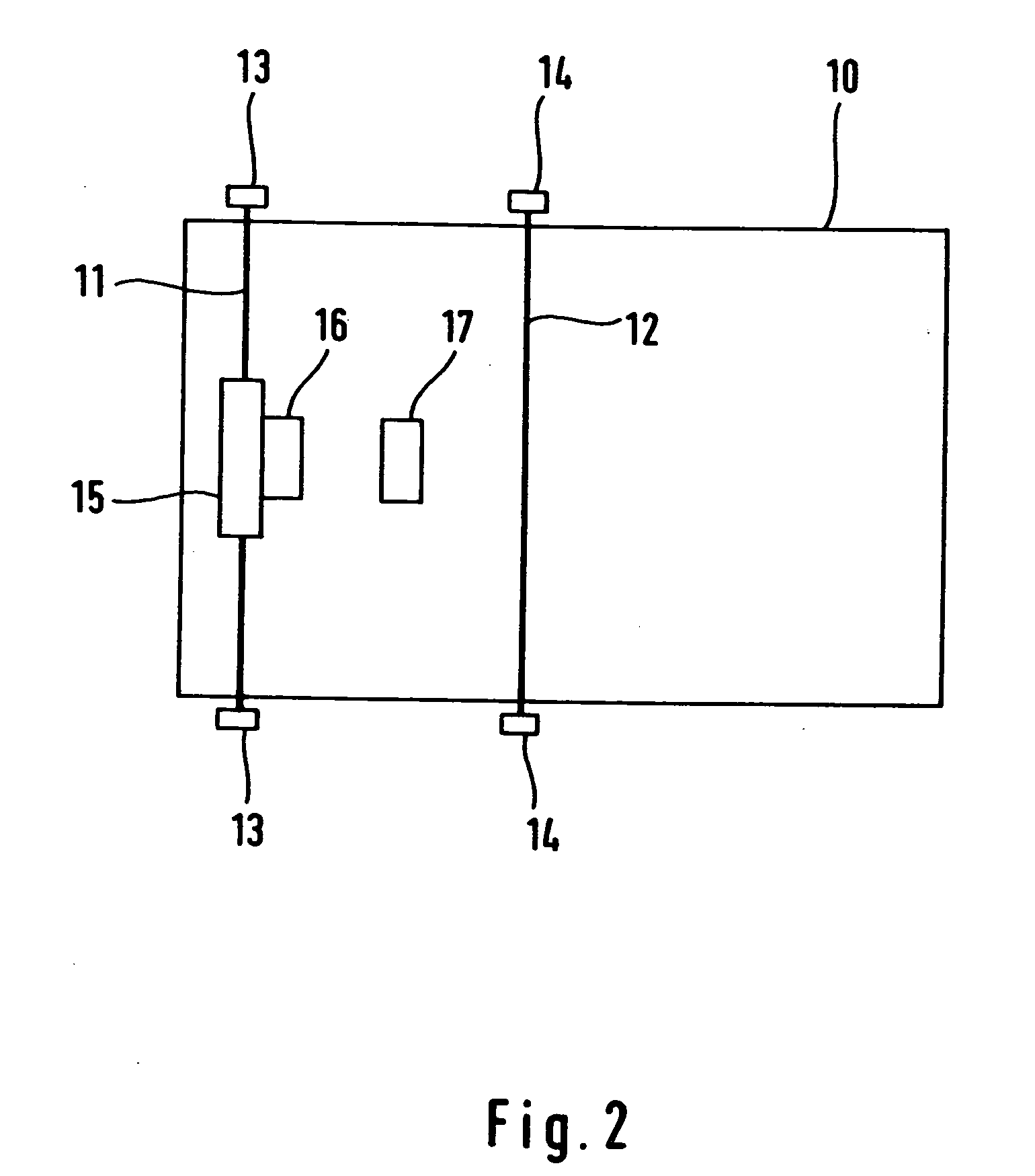
[0039] FIG. 2 shows an embodiment form of loading floor 10, for use in vehicle 1 from FIG. 1. Loading floor 10 consists of, for exam...


PUM


Abstract

A loading floor for a vehicle having first guide elements for engaging second guide elements of the vehicle, for lifting and extending a loading floor. The first guide elements are provisioned at the sides of the loading floor. A loading apparatus for a vehicle having a loading area with two sidewalls that border the loading area. Guide elements are provided for lifting and extending a loading floor, where the guide elements are provisioned on or in the sidewalls above the vehicle floor.

Description

[0001] This application is a continuation of International Application No. PCT / EP03 / 03072, Mar. 25, 2003, the contents of which are here incorporated by reference in their entirely.[0002] 1. Field of the Invention[0003] The invention relates to a loading apparatus in general, and more particularly to a loading floor for a vehicle.[0004] 2. Prior Art[0005] Various pull-out loading floors and loading apparatuses are known from the state of the art. A pull-out loading surface for station wagons is known from DE-OS 23 02 972, wherein guide rails are provisioned on the loading surface of the vehicle. The pull-out loading surface is mounted on these guide rails and can be moved on the guide rails on rollers. The items to be loaded can then be set onto the pulled out loading surface and pushed into the loading area of the vehicle.[0006] A loading apparatus for personal vehicles or transportation vehicles is known from DE 296 08 955 U1. This loading apparatus consists of a guide element tha...

Claims


Application Information

Patent Timeline
Patent Type & Authority Applications(United States)
IPC IPC(8): B60P1/00B60R5/04
CPCB60R5/04B60P1/003
Inventor NICK, ALBRECHTTHOMA, WULFSCHWARZ, WERNER
Owner FAURECIA INNENRAUM SYST
Why Eureka
Try Eureka