Decorative wall covering with upward movement panel interlock system

Inactive Publication Date: 2004-08-19
NOVIK INC
View PDF23 Cites 22 Cited by
  • Summary
  • Abstract
  • Description
  • Claims
  • Application Information

AI Technical Summary

Benefits of technology

0005] It is an object of the present invention to provide a plastic wall or roof pane

Problems solved by technology

Leakage problems between adjoining panels also can occur.
Heretofore the provision and use of side interlocks in such simulated building panels has created installation problems.
Hence, engaging of both the upper, lower, and side interlocks has required cumbersome manipulation of the panel.
Moreover, wh

Method used


Image

  • Decorative wall covering with upward movement panel interlock system
  • Decorative wall covering with upward movement panel interlock system
  • Decorative wall covering with upward movement panel interlock system

Examples


Embodiment Construction

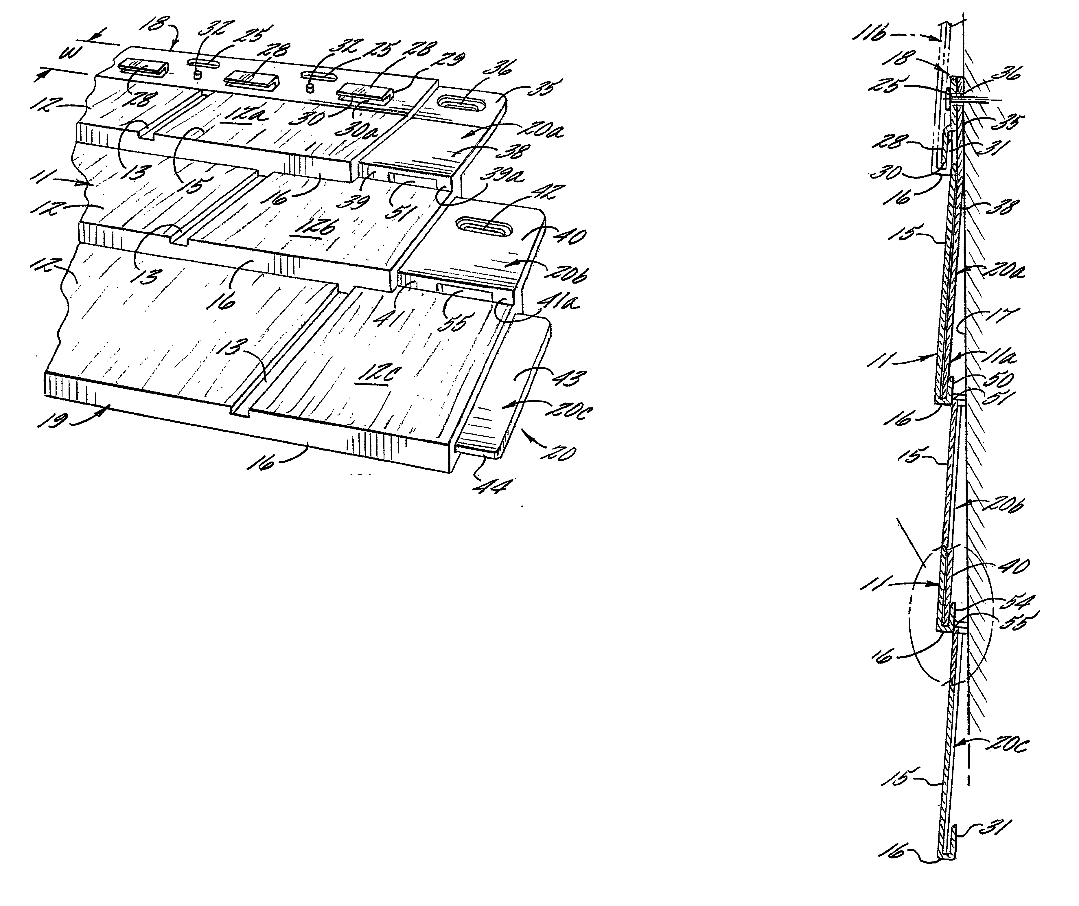
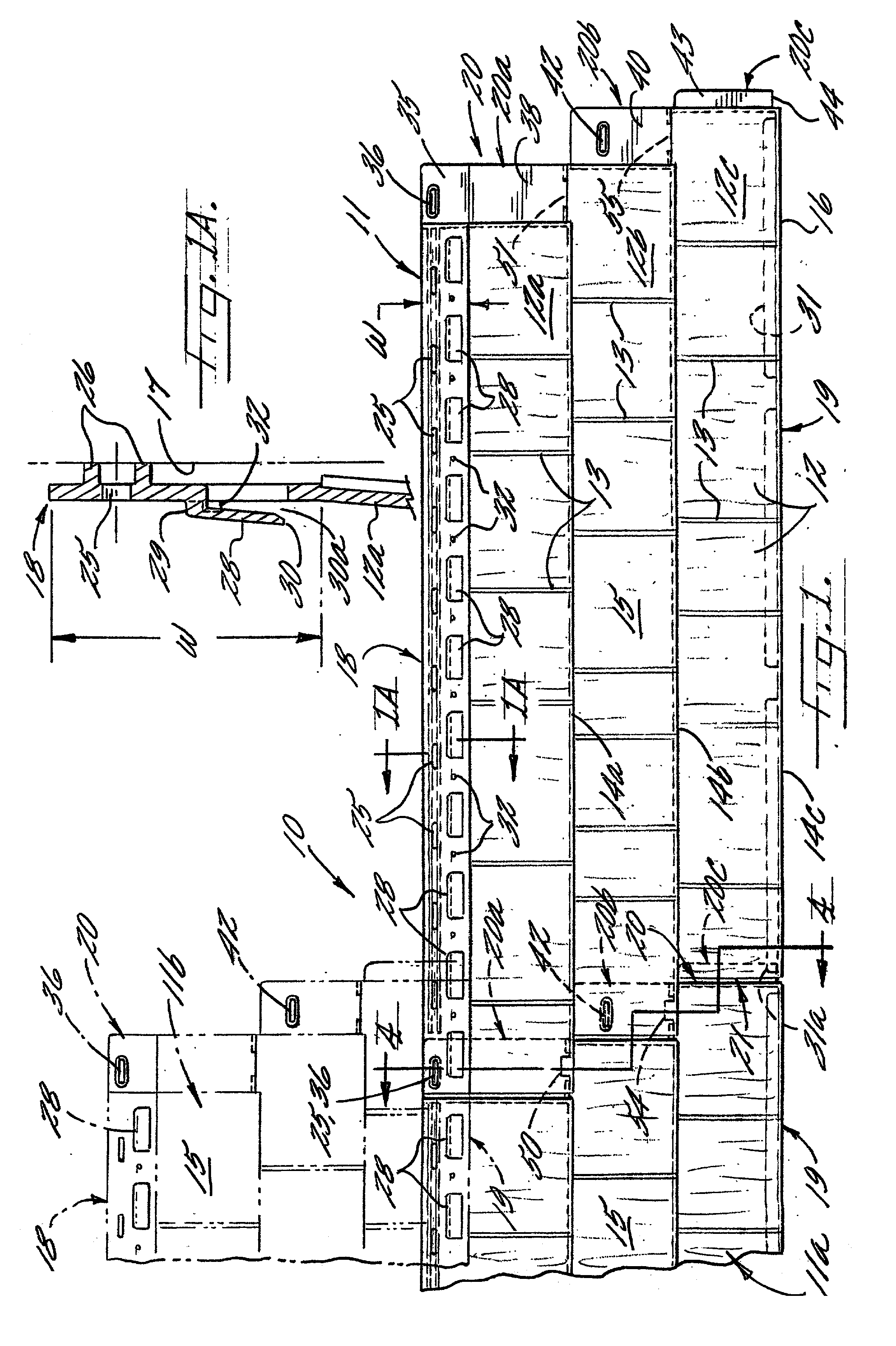
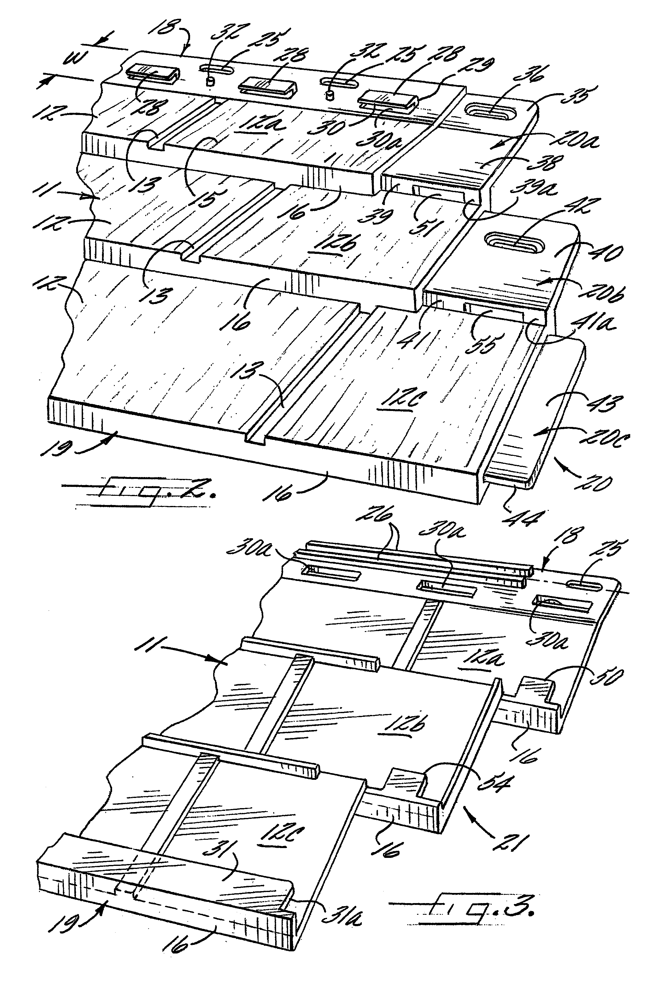
[0023] Referring now more particularly to FIG. 1 of the drawings, there is shown an illustrative wall covering 10 comprising a plurality of panels 11 in accordance with the present invention. The general type of panel employed in the instant invention is described in commonly assigned U.S. Pat. Nos. 5,347,784 and 5,537,792, the disclosures of which are incorporated herein by reference. As shown in FIG. 1, the panels 11 each are formed with simulated building elements. In this instance, the panels 11 are formed with simulated cedar shake 12 of irregular width which are disposed in three parallel rows 12a, 12b, 12c with adjacent shake 12 in each row being separated by a small gap 13. The illustrated simulated shake pattern is of a type known in the industry as "perfection" shake, wherein the lower edges 14a, 14b, 14c of the rows 12a, 12b, 12c are in a substantially straight line, and except for their width, the individual shake elements are substantially similar in appearance.

[0024] T...


PUM


Abstract

A wall covering comprising a plurality of plastic panels each having a body portion formed with rows of simulated building elements. The panels are mounted on a support surface with a lower marginal edge region of one panel overlying an upper marginal edge region of a previously mounted panel in a lower course and with a side marginal edge region of one panel overlying the side marginal edge region of a previously mounted adjacent panel in the same course. The marginal edge regions are provided with interlocks which engage and secure both the overlapping upper and lower marginal edge regions and the overlapping side marginal edge regions as an incident to upward movement of the panel relative to the underlying previously mounted panels. In the illustrated embodiment, the overlying lower marginal edge region and side marginal edge region of each panel are formed with upwardly directed locking flanges which are respectively engageable with downwardly directed flanges on the upper marginal edge region and apertures in the side marginal edge region of the underlying panels.

Description

[0001] The present invention relates generally to roof and wall coverings which are primarily intended for outdoor usage, and more particularly, to roof and wall coverings comprised of relatively large panels which each are molded or otherwise formed with decorative patterns characteristic of conventional roofing and siding materials, such as shake shingles, tile, brick or the like.[0002] Various synthetic roof and wall coverings are known today which are formed of elongated thermoplastic panels that are nailed to a wall or roof support surface in horizontal courses or rows in partially overlapping relation to each other so as to provide a substantially water resistant, protective layer over the support surface. Such panels, which usually are identically molded, commonly are formed with a plurality of rows of simulated building elements, such as shake shingles. Because the panels are identically molded, a panel-to-panel identity can be easily noticed if the panels are not carefully ...

Claims


Application Information

Patent Timeline
IPC IPC(8): E04F13/08E04F13/18
CPCE04F13/18E04F13/0864
Inventor DONLIN, TERENCE JAMESGUZZO, FRANCESCO
Owner NOVIK INC
Why Eureka
Try Eureka