

Actuator apparatus and method for improved deflection characteristics
a technology of actuators and deflection characteristics, applied in the direction of instruments, braking systems, braking components, etc., can solve the problems of impracticality in practice, inability to provide good deflection characteristics of actuators in the prior art, and all previous solutions have serious drawbacks, and achieve the effect of minimal actuation for
Inactive Publication Date: 2004-08-19
KNOLLENBERG CLIFFORD F +1
View PDF11 Cites 70 Cited by
- Summary
- Abstract
- Description
- Claims
- Application Information
AI Technical Summary
Benefits of technology
[0012] It is therefore an object of the present invention to provide an actuator that can be operated over large deflections with minimal actuation force.
Problems solved by technology
Several designs have been invented in an attempt to provide acceptable deflection characteristics for such devices, however all previous solutions have serious drawbacks.
However, the folded suspension as documented has considerable limitations that make it impractical in practice.
In summary, the prior art does not provide good deflection characteristics for actuators moving substantially perpendicular to a substrate.
For any actuator using electrostatic forcing, minimizing the voltage required for actuation is desirable as high voltage circuits are both expensive and complicated.
On the other hand, this has increased the voltage requirements for actuation.
As discussed above, if the stiffness of the attachment portion is too great, it will decrease the overall deflection / elevation of the bimorph flexures and cause unwanted bowing of the actuator segment electrode.
Above 4 .mu.m, the fabrication process is rendered too complex, time-consuming and expensive.
In many applications with tight spacing requirements such as deformable mirror arrays or optical crossconnect switches, this rotation can be detrimental as adjacent actuators could touch.
Method used
View moreImage
Smart ImageViewing Examples

Examples
Embodiment Construction
has been presented for purposes of illustration and description. It is not intended to be exhaustive or to limit the invention to the precise form disclosed. Many modifications and variations are possible in light of the above teaching. The described embodiments were chosen in order to best explain the principles of the invention and its practical application to thereby enable others skilled in the art to best utilize the invention in various embodiments and with various modifications as are suited to the particular use contemplated. It is intended that the scope of the invention be defined by the claims appended hereto.
Login to View More PUM
 Abstract
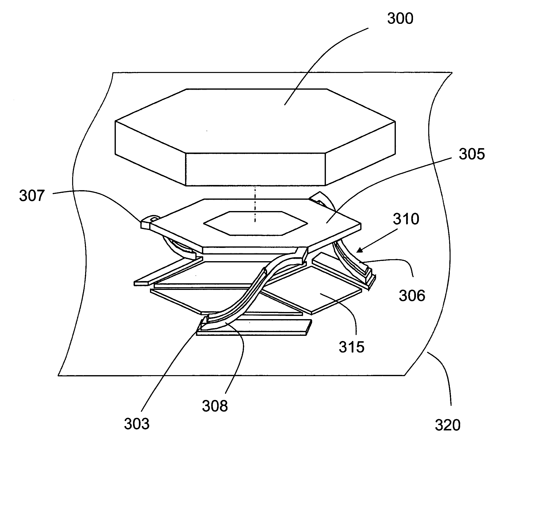
A micromachined actuator including a body or platform mounted to a suspension system anchored to a substrate. In one embodiment, the suspension system is comprised of a set of one or more spring flexures connecting the actuator body to the substrate with strain relief provided via connecting torsional elements. In another embodiment, the suspension system includes a first set of one or more spring flexures each with one end anchored to a largely rigid intermediate frame and the other end attached to the body. A second set of one or more flexures is attached between the intermediate frame and the substrate. A third actuator embodiment maximizes force electrode area to minimize voltage required for electrostatic actuation. A fourth embodiment provides electrical interconnect to an actuator or an actuator array using polysilicon with silicon nitride isolation. Actuators may be fabricated by combining the key features of all four embodiments or actuators may be fabricated using any combination of two or three of the embodiments.
Description
[0001] This application claims the benefit of U.S. Provisional Patent Application No. 60 / 425,049 entitled Reduced Rotation MEMS Deformable Mirror Apparatus and Method, and U.S. Provisional Patent Application No. 60 / 425,051 entitled Deformable Mirror Method and Apparatus Including Bimorph Flexures and Integrated Drive, both filed Nov. 8, 2003.[0002] 1. Field of the Invention[0003] This invention relates to micro-fabricated actuators, and more particularly relates to improving long-stoke deflection characteristics.[0004] 2. Description of the Related Art[0005] The advent of micromachining has enabled the economic fabrication of tiny precision micro-actuators and micromachines using techniques first pioneered in the semiconductor industry. Micro-fabricated actuators with long stoke are used in a diverse range of applications including adaptive optics, disk drives, fluidic valves, video displays, and micro-positioning.[0006] Microfabricated actuators are often comprised of an actuation ...
Claims
Login to View More Application Information
Patent Timeline
 IPC IPC(8): G02B26/06G02B26/08H01H59/00
CPCG02B26/06G02B26/0825H01H59/0009B81B2203/056B81B2203/0163B81B3/0037B81B2203/053H01H2059/0081
InventorKNOLLENBERG, CLIFFORD F.HELMBRECHT, MICHAEL ALBERT
OwnerKNOLLENBERG CLIFFORD F