Key agreement system, shared-key generation apparatus, and shared-key recovery apparatus

a technology of shared keys and agreement systems, applied in the field of key agreement systems and shared key generation apparatuses, can solve problems such as decrypted text and the inability of reception apparatuses to derive the same shared key k

Inactive Publication Date: 2004-09-09
PANASONIC CORP
View PDF3 Cites 31 Cited by
  • Summary
  • Abstract
  • Description
  • Claims
  • Application Information

AI Technical Summary

Benefits of technology

[0048] The object of the present invention, in view of the above-described problems, is to provide a key agreement system, a shared-key generation apparatus, a shared-key recovery apparatus, a shared-key generating method, a shared-key recovery method, a shared-key generating program, and a shared-key recovery program, which prevents derivation of different keys between the shared-key generation apparatus and the shared-key recovery apparatus.
[0119] According to this construction, the shared-key recovery apparatus decrypts the received encrypted content, using the outputted decryption shared key, to generate a decrypted content. Therefore, there is an effect that a content is received from the shared-key generation apparatus, in secrecy.

Problems solved by technology

However, the mentioned processes have a possibility of yielding decrypted text that is different from the original plaintext.
On the contrary, other reception apparatuses that do not know about the secret key sk cannot obtain the element s from the cipher text C, even if they have acquired the public key pk and received the cipher text C. This means that these reception apparatuses cannot derive the same shared key K as that derived by the transmission apparatus.

Method used


Image

  • Key agreement system, shared-key generation apparatus, and shared-key recovery apparatus
  • Key agreement system, shared-key generation apparatus, and shared-key recovery apparatus
  • Key agreement system, shared-key generation apparatus, and shared-key recovery apparatus

Examples


first embodiment

[0274] The first embodiment described above is one example of carrying out the present invention. Needless to say, the present invention is not limited to this particular embodiment, and can be carried with various modifications as long as they are within the scope of the present invention. In light of this, the following cases are included in the present invention.

[0275] (1) The Parameter N to be Used in NTRU Cryptosystem May Take Other Value than 167.

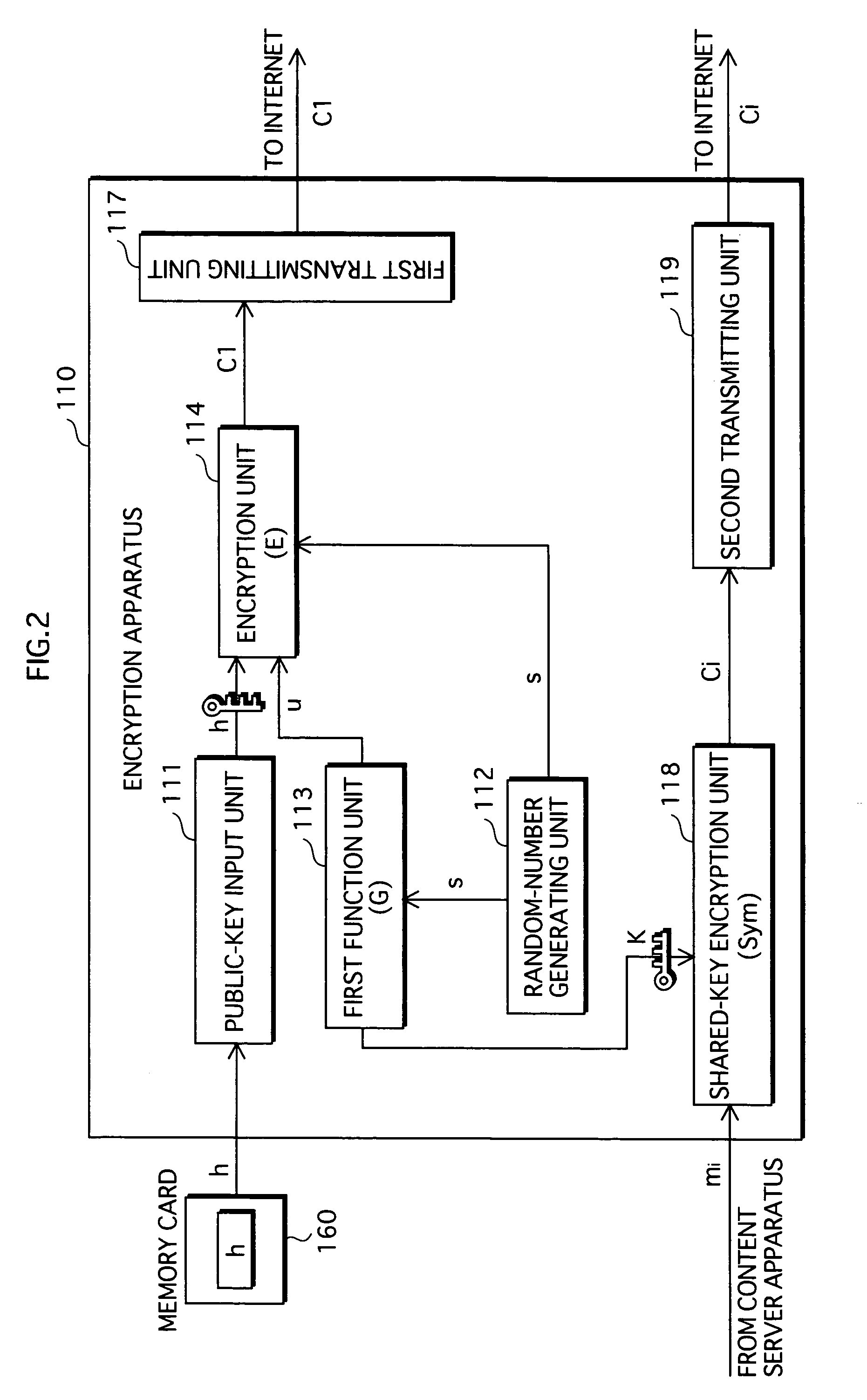
[0276] (2) The conversion method between the element of each bit in the bit sequence and the coefficient of each term in the polynomial, which is performed in the encryption unit 114 and the decryption unit 123, is not limited to the aforementioned method, and may be other methods.

[0277] For example, the conversion of the random number s to the random-number polynomial sp may be performed using a function that corresponds the element of each bit in the bit sequence to the coefficient of each term in the polynomial, in one-to-one relat...

second embodiment

[0325] 2. Second Embodiment

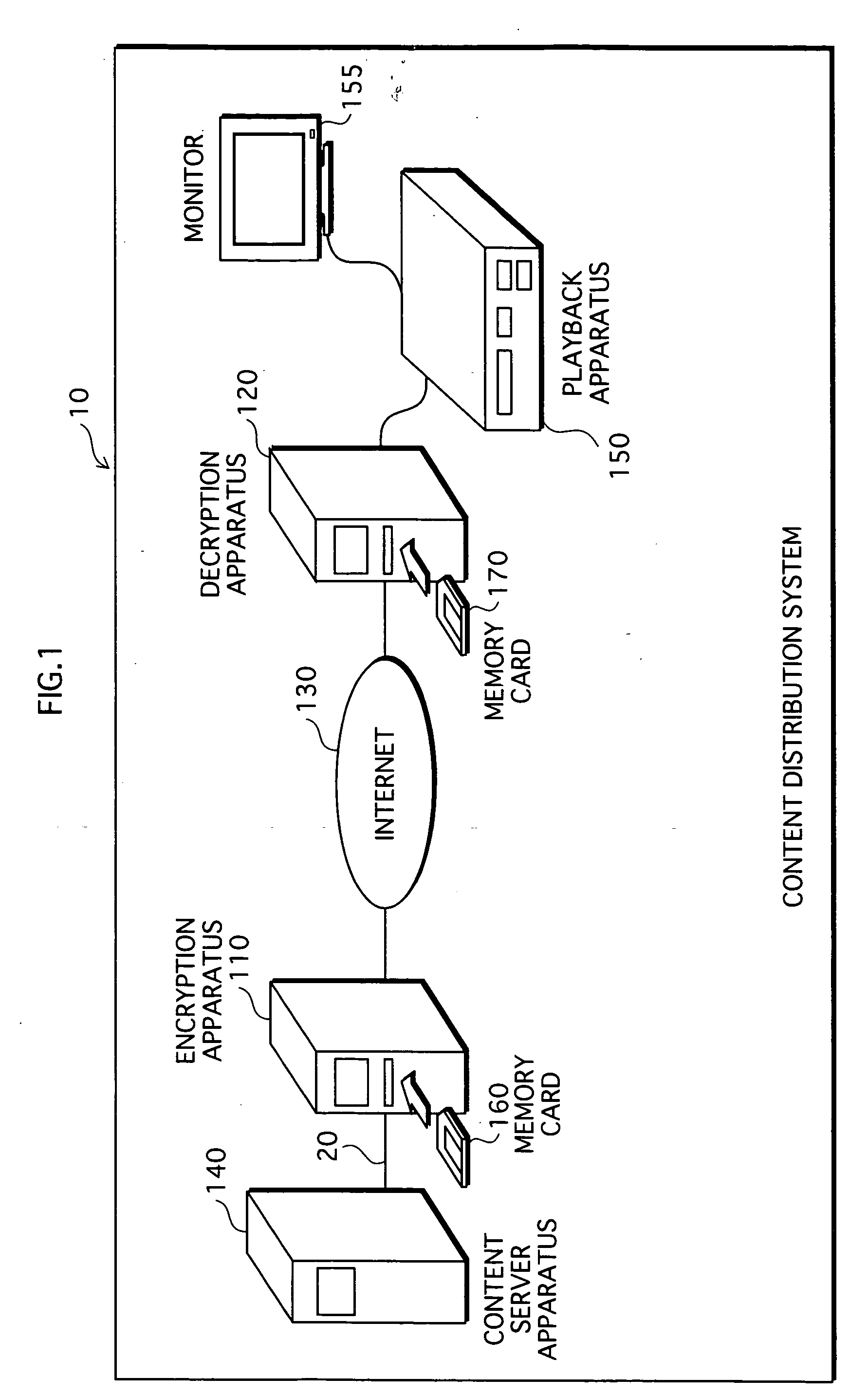
[0326] The following describes a content distribution system 10c (unshown in any drawing), as another embodiment relating to the present invention.

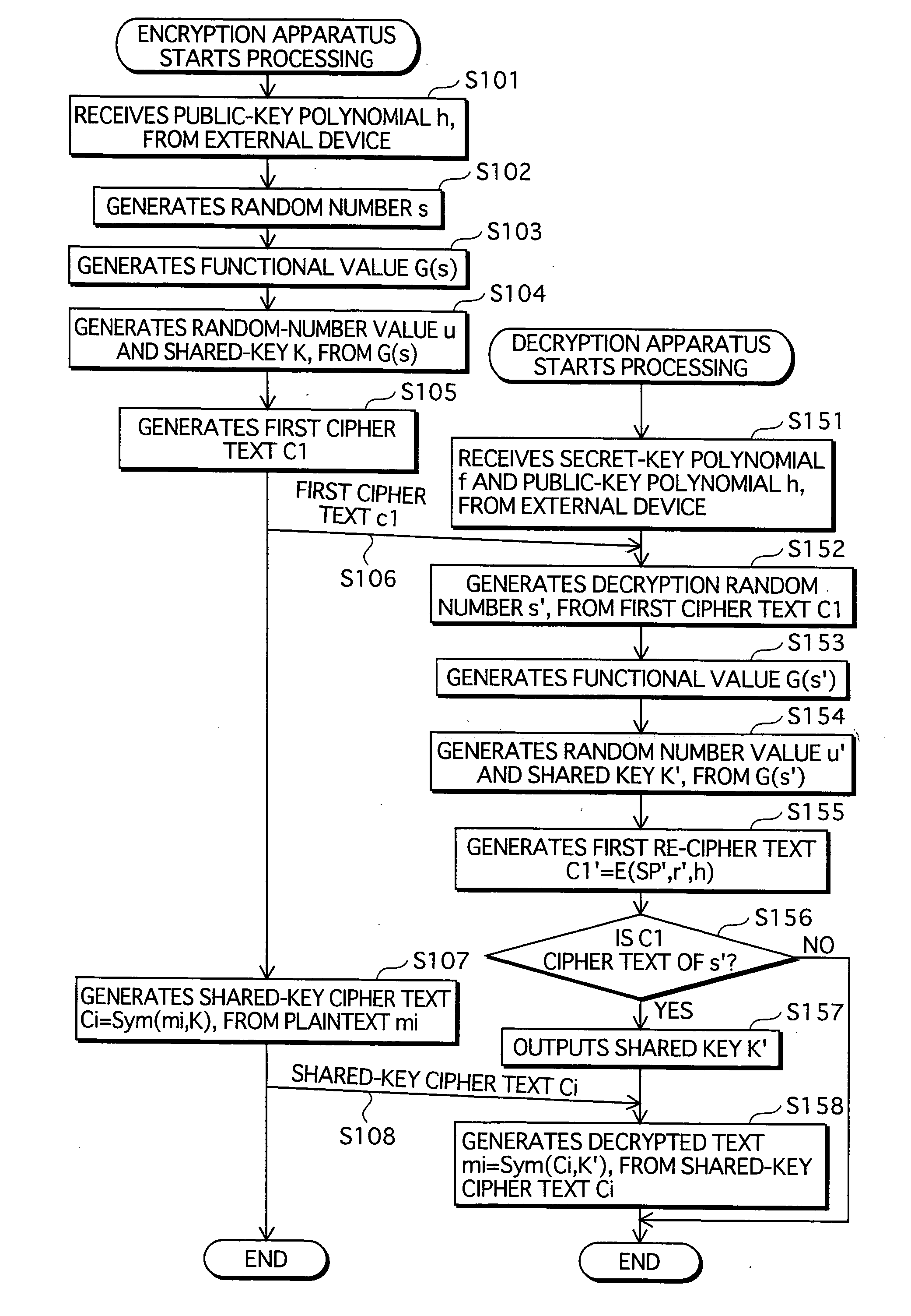
[0327] The content distribution system 10c is a system based on the content distribution system 10 with some modifications. The differences with the content distribution system 10 are that: a verification value a is generated from G(s), in addition to the random-number value u and the shared key K; and the encryption apparatus, instead of generating the first cipher text by encrypting the random number s and transmitting it, generates a first cipher text c1 resulting from encrypting the verification value a, and a second cipher text c2 resulting from encrypting the random number s based on the verification value a, and transmits the first cipher text c1 and the second cipher text c2.

[0328] The following description focuses on the differences mentioned above.

[0329] 2.1 Structure of Content Distribution System 10c...

third embodiment

[0444] 4. Third Embodiment

[0445] The following describes a content distribution system 10d (unshown in any drawing), as another embodiment relating to the present invention.

[0446] The content distribution system 10d is a system resulting by modifying the content distribution system 10. The following describes the content distribution system 10d, focusing on the differences with the content distribution system 10.

[0447] 4.1 Structure of content distribution system 10d

[0448] The content distribution system 10d has the similar structure as the content distribution system 10, except that the encryption apparatus 110 and the decryption apparatus 120 are replaced by an encryption apparatus 110d and a decryption apparatus 120d, respectively. The other components are the same as those included in the content distribution system 10, therefore whose explanation is omitted here.

[0449] The content distribution system 10d is a cryptographic communication system that performs cryptographic commun...


PUM


Abstract

Provided is a content distribution system that prevents different keys to be derived between an encryption apparatus and a decryption apparatus. A random-number generating unit 112, in an encryption apparatus 110, generates a random number s. A first function unit 113 generates a functional value G(s) of the random number s, and generates a random-number value u and a shared key K from the functional value G(s). An encryption unit 114 generates a first cipher text c1 of the random number s, using a public-key polynomial h and the random-number value u. A decryption unit 123, in a decryption apparatus 120, decrypts the first cipher text c1 using a secret-key polynomial f, to generate a decryption random number s' A second function unit 126 generates a functional value G(s') of the decryption random number s', and generates a random-number value u' and a shared key K'from the functional value G(s' ). A comparison unit 127 generates a first re-cipher text c1', using the random-number value u' and the shared key K', and outputs the shared key K' if the first cipher text c1 is equal to the first re-cipher text c1'.

Description

[0001] 1. Field of the Invention[0002] The present invention relates to a cryptographic technology used as an information security technology. The present invention particularly relates to a technology of distributing a key under a condition that any third party cannot know the content of the key.[0003] 2. Description of Related Art[0004] Conventionally, the public-key cryptosystem has been used for transmitting information from a transmission apparatus to a reception apparatus in secrecy.[0005] In the public-key cryptosystem, a transmission apparatus encrypts a communication content using the public key of a reception apparatus, and sends the encrypted communication content to the reception apparatus. The reception apparatus receives the encrypted communication content, and decrypts the encrypted communication content using a secret key, thereby obtaining the original communication content (e.g. refer to the non-patent reference 1).[0006] In the year of 1996, the NTRU cryptosystem ...

Claims


Application Information

Patent Timeline
Patent Type & Authority Applications(United States)
IPC IPC(8): H04L9/08H04L9/30
CPCH04L9/085H04L2209/60H04L2209/04H04L9/0869H04L9/08H04L9/30G09C1/00
Inventor YAMAMICHI, MASATOYAMAMICHI, MASAMIFUTA, YUICHIOHOMORI, MOTOJITATEBAYASHI, MAKOTO
Owner PANASONIC CORP
Why Eureka
Try Eureka