Thermal head printer and process for printing substantially light-insensitive recording materials

Active Publication Date: 2004-09-23
AGFA NV
View PDF4 Cites 3 Cited by
  • Summary
  • Abstract
  • Description
  • Claims
  • Application Information

AI Technical Summary

Benefits of technology

[0015] It is therefore an aspect of the present invention to provide a means to avoid failure of the heating elements due to overheating and to avoid such image faults in the thermographic materials due to overheating without significant loss in image information.
[0016] It is a further aspect of the present invention to provide a thermal head printer capable of printing a substantially light-insensitive thermographic material without unacceptable heating element failure and image faults in the thermographic materials due to overheating without significant loss in image information.
[0017] It is also an aspect of the present invention to provide a calibration process for printing a substantially light-insensitive thermographic material to avoid failure of the heating elements due to overheating and to avoid such image faults in the thermographic materials due to overheating without significant loss in image information during the printing of the thermographic material.

Problems solved by technology

The electronic circuit breaker provides a current limit function and will not allow a current greater than a predetermined amperage level to be drawn.
Attaining such high print densities in thermographic materials requires that the heating elements be driven at higher powers and hence to higher temperatures, which increases the probability of premature heating element failure due to overheating and of image faults in the thermographic materials due to overheating.

Method used


Image

  • Thermal head printer and process for printing substantially light-insensitive recording materials
  • Thermal head printer and process for printing substantially light-insensitive recording materials
  • Thermal head printer and process for printing substantially light-insensitive recording materials

Examples


invention example 1

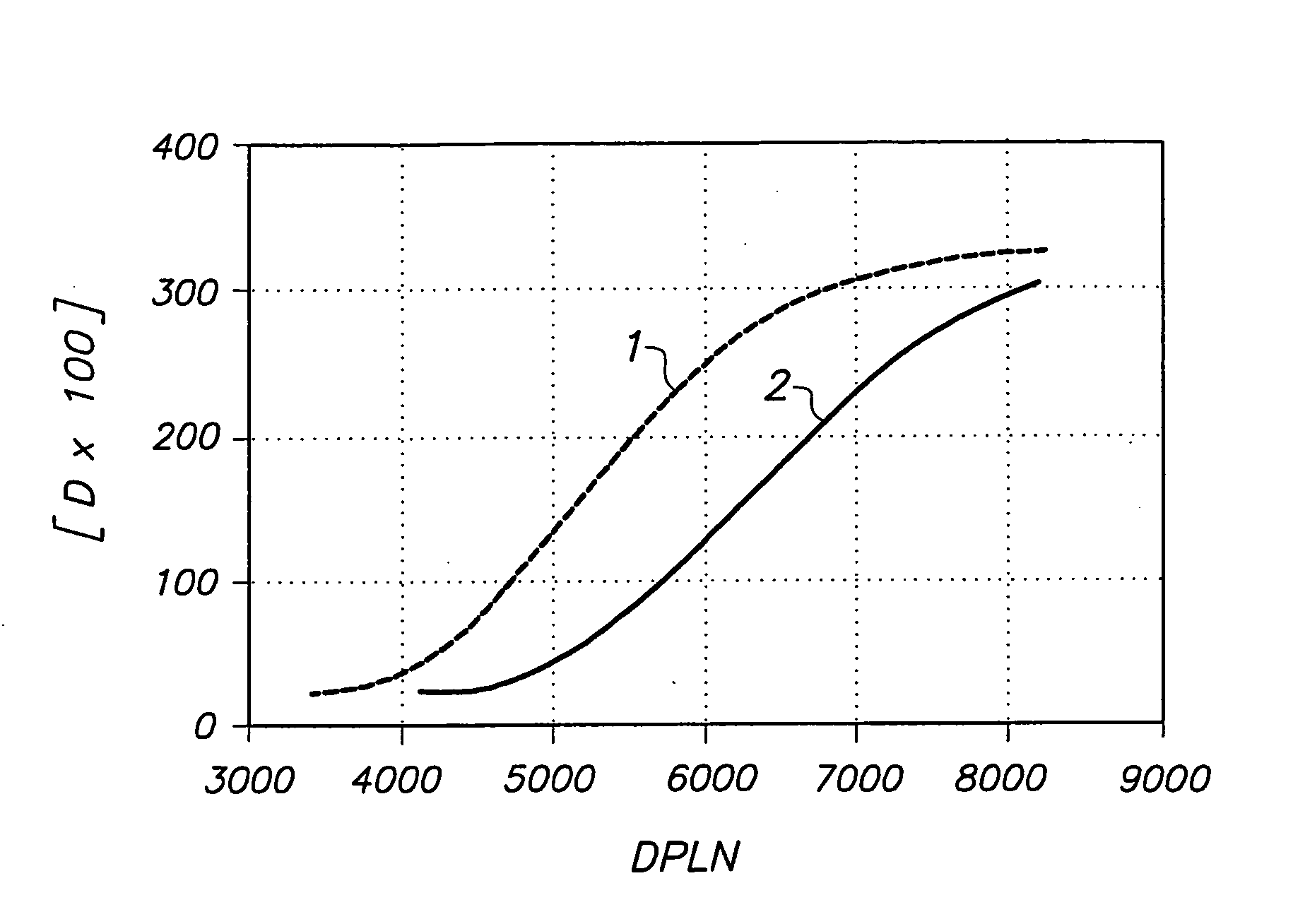
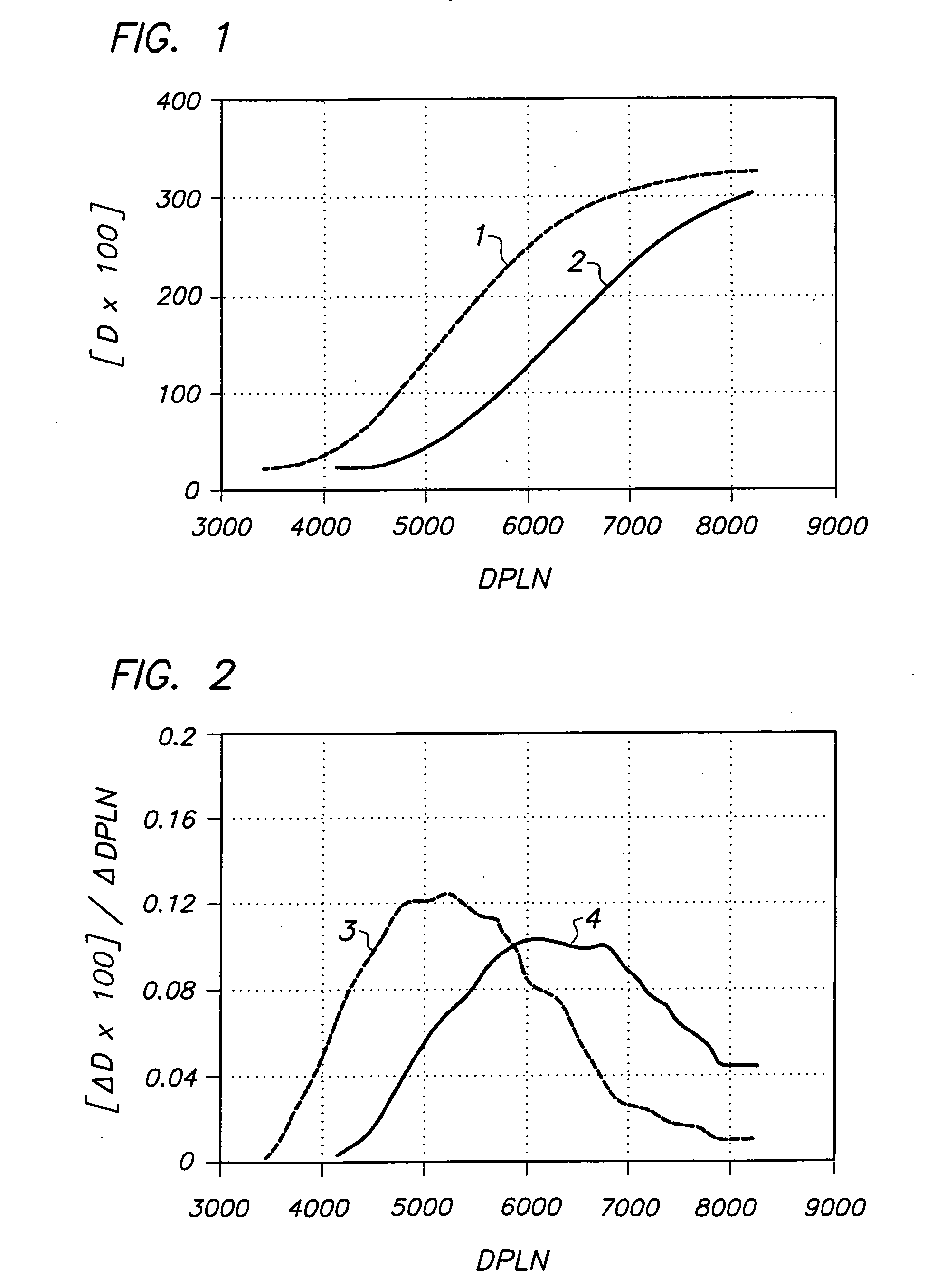
[0107] Four step-wedges were simultaneously printed with the type 1 substantially light-insensitive thermographic material in an environment with a temperature of 25.degree. C. and a relative humidity of 50% relative humidity with a DRYSTAR.TM. 4500 M printer with a line time of 7 ms from AGFA-GEVAERT N.V. consisting each of 13 areas 4 mm in width and ca. 200 mm in length along the transport direction of the printer with a maximum power level of 38.2 mW. Each of the 52 areas was printed at a different DPLN from a total number of 13 bit (8192) with each of the 13 areas covering the whole DPLN range. The optical densities were measured with a built in dynamic transmission densitometer with a spot size of 0.6 mm by taking the average of 10 measurements. The densitometer scanned over the areas at substantially 90.degree. to the transport direction with the substantially light-insensitive thermographic material stationary. The four sets of print density-DPLN data were combined into a sin...

invention example 2

[0110] Four step-wedges were simultaneously printed with the type 2 substantially light-insensitive thermographic material in an environment with a temperature of 25.degree. C. and a relative humidity of 50% relative humidity with a DRYSTAR.TM. 4500 printer with a line time of 7 ms from AGFA-GEVAERT N.V. consisting each of 13 areas 4 mm in width and ca. 200 mm in length along the transport direction of the printer with a maximum power level of 47.6 mW. Each of the 52 areas was printed at a different DPLN from a total number of 13 bit (8192) with each of the 13 areas covering the whole DPLN range. The optical densities were measured with a built in dynamic transmission densitometer with a spot size of 0.6 mm by taking the average of 10 measurements. The densitometer scanned over the areas at an angle of substantially 90.degree. to the transport direction with the substantially light-insensitive thermographic material stationary. The four sets of print density-DPLN data were combined ...

invention example 3

[0113] Two step-wedges consisting each of 16 areas, 337 mm in width and ca. 9.5 mm in length along the transport direction of the printer were simultaneously printed on the type 1 substantially light-insensitive thermographic material at a temperature of 25.degree. C. and a relative humidity of 50% with a DRYSTAR.TM. 5300 printer from AGFA-GEVAERT N.V. with a maximum power level of 62.4 mW and a line time of 8,35 ms. Each of the 32 areas was printed at a different DPLN from a total number of 13 bit (8192) with the 16 areas covering the whole DPLN range. The optical densities were measured with a built-in static transmission densitometer with a spot size of 30.times.70 mm by taking the average of 13 measurements. The densitometer scanned over the areas in the transport direction while the substantially light-insensitive thermographic material moved to the output tray. The two sets of print density-DPLN data were combined into a single smoothed master curve and the dependence of slope...


PUM


Abstract

A thermal head printer with image-invariant printing speeds for printing a substantially light-insensitive thermographic material having a print density-driving power level characteristic, the thermal head printer comprising a transport means, one or more thermal heads each having an array of heating elements, a thermal print head drive system capable of supplying power to each of the printing elements, and a calibration means based on the print density-driving power level characteristic of the thermographic material; a process for calibrating a thermal head printer with image-invariant printing speeds, the thermal head printer comprising one or more thermal heads each having an array of heating elements connected to a power supply capable of supplying a given number of heating element driving power levels from 0 to a maximum driving power level number, corresponding to Pmax, to each heating element for printing a substantially light-insensitive thermographic material by image-wise heating the thermographic material with the heating elements, the process comprising the steps of: (i) putting the printer into a calibration mode; (ii) printing one or more step-wedges of print densities by heating the thermographic material with the heating elements at different DPLN'S; (iii) determining the optical density of each step of the step-wedge(s) of print densities with a densitometer thereby obtaining the dependence of the print density upon DPLN; (iv) deriving from the dependence, or all the dependences of the print density upon DPLN, a single smoothed dependence of the rate of change of print density, D, with DPLN, DeltaD / DeltaDPLN, as a function of DPLN for the thermographic material; (v) establishing a threshold rate of print density change per DPLN for the specific thermographic material being printed; and (vi) setting up the thermal head printer so that the threshold rate of print density increase per DPLN cannot be undercut; and a process for printing a substantially light-insensitive thermographic material with a thermal head printer comprising one or more thermal heads each having an array of heating elements connected to a power supply capable of supplying a given number of heating element driving power levels from 0 to a maximum driving power level number, corresponding to Pmax, the process comprising the steps of: calibrating the thermal head printer according to the above-described calibration process, transporting the substantially light-insensitive thermographic material past the thermal head, and image-wise heating of the substantially light-insensitive thermographic material by means of the heating elements.

Description

CROSS-REFERENCE TO RELATED PATENT APPLICATIONS[0001] This application claims the benefit of U.S. Provisional Application No. 60 / 459,657 filed Apr. 2, 2003, which is incorporated by reference. In addition, this application claims the benefit of European Application No. 03100622.4 filed Mar. 12, 2003, which is also incorporated by reference.[0002] The present invention concerns a process for calibrating a thermal head printer for use with a substantially light-insensitive recording material.[0003] Thermography is an image-forming process including a heating step and hence includes photothermography in which the image-forming process includes image-wise exposure and direct thermal processes in which the image-forming process includes an image-wise heating step.[0004] In direct thermal printing a visible image pattern is produced by image-wise heating of a recording material e.g. image signals can be converted into electric pulses and then via a driver circuit selectively transferred to...

Claims


Application Information

Patent Timeline
IPC IPC(8): B41J2/36
CPCB41J2/36
Inventor DE MEUTTER, STEFAANKAERTS, ERIC
Owner AGFA NV
Why Eureka
Try Eureka