
E-line downhole jarring tool

a jarring tool and e-line technology, applied in the field of downhole tools, can solve the problems of large tools, complex and expensive, and failure to loosen the work string, and achieve the effect of small and simple apparatus

Active Publication Date: 2004-09-30
IMPACT SELECTOR INT LLC
View PDF8 Cites 5 Cited by
  • Summary
  • Abstract
  • Description
  • Claims
  • Application Information

AI Technical Summary

Benefits of technology

[0009] Still another object of the invention is to provide a device that is small and easily transported.
[0011] According to the present invention, the invention is an electrical line downhole tool for manipulating a work string which is easily configured to deliver a specific amount of force to the work string in a small and simple apparatus.

Problems solved by technology

Consequences of failure to remove the obstruction can be failure of the well to produce at all or in part, also, current methods of removing obstructions can result in failure to loosen the work string, both of which result in having to relocate the drilling operation, which necessarily involves lost time and money.
These tools are generally large, complex and expensive, and many are not easily configured to apply varying amounts of force to the work string, which can result in imprecise application of energy to the work string.
This, in turn, can break or otherwise damage the work string, resulting in a requisite move of a project, or at the very least, lost time and energy in repairing the work string.
It is known in the art to apply force to dislodge a work string, however the current devices in this field do not offer the unique combination of the small, simple and configurable characteristics inherent in the configuration presented herein.

Method used


Image

  • E-line downhole jarring tool
  • E-line downhole jarring tool
  • E-line downhole jarring tool

Examples


Embodiment Construction

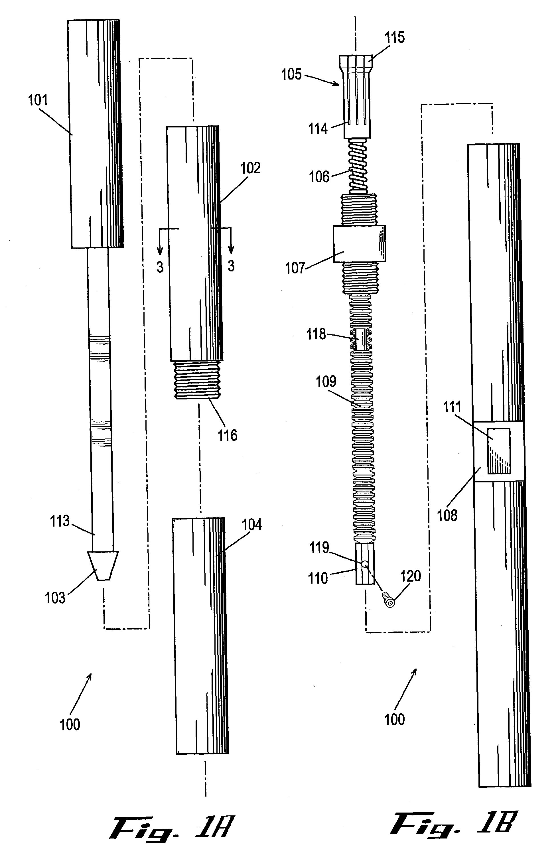
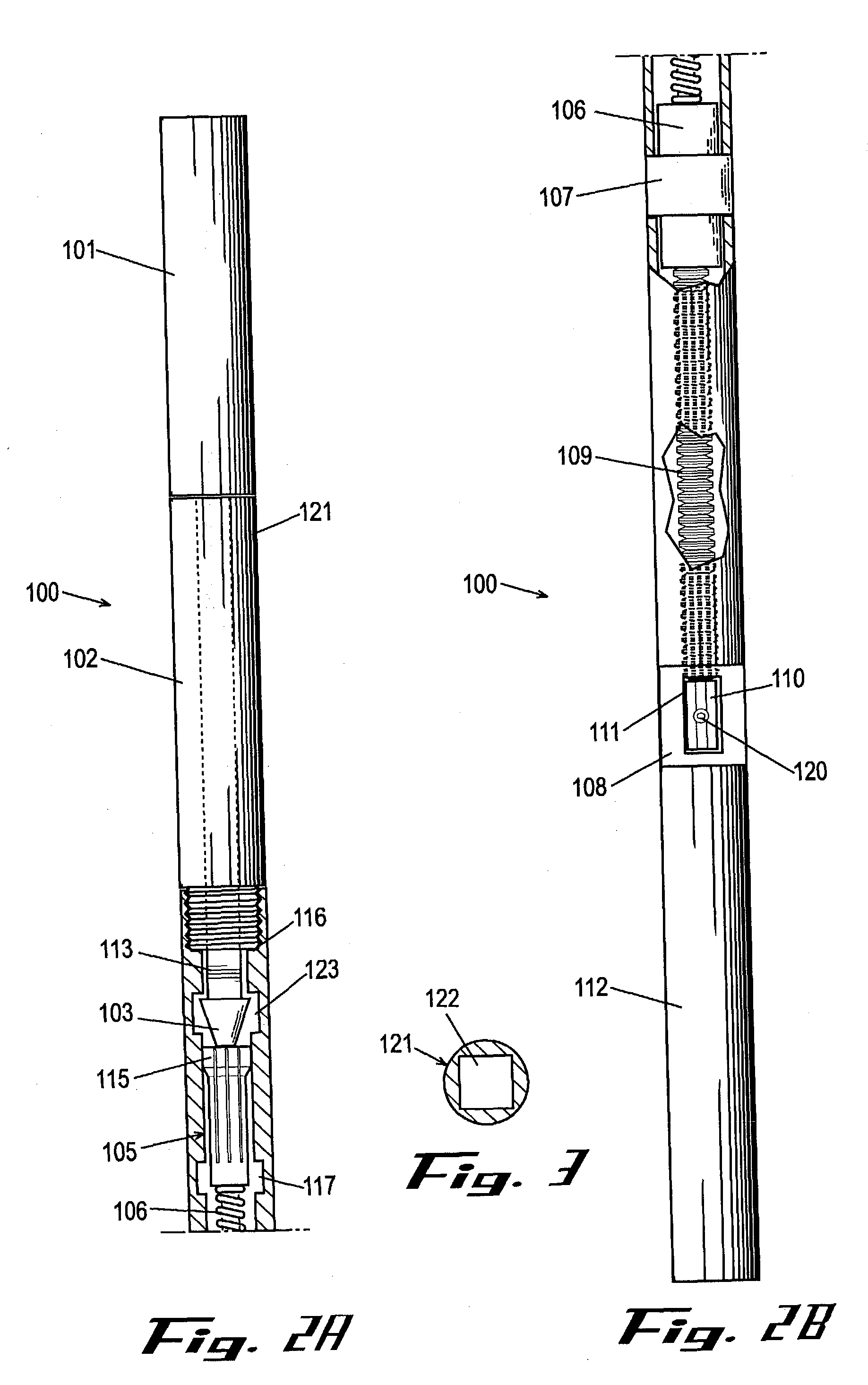
[0018] Without any intent to limit the scope of this invention, reference is made to the figures in describing the various embodiments of the invention. Referring to FIGS. 1 through 3, line downhole jarring tool 100 is pictured.

[0019] Jarring tool 100 has a hammer mandrel 101 near the top end of jarring tool 100 which is formed with shaft 113 extending from the bottom end of hammer mandrel 101. Shaft 113 can be formed such that a portion of shaft 113 has beveled sides, providing a flat surface that permits the shaft to be turned with a wrench, as well as forming a "keyed" relationship with the square opening 122 of retaining mandrel 102's aligning collar 121. This "keyed" relationship prevents relational torquing between shaft 113 and retaining mandrel 102. This arrangement also precludes the need for aligning screws or other components, which detract from the simplicity and effectiveness of a tool.

[0020] At the end of shaft 113, shaft 113 forms a releasable bolt 103 which can be sh...


PUM


Abstract

According to the present invention, the e-line downhole jarring tool is an electrical line downhole tool for manipulating a work string which is easily configured to deliver a specific amount of force to the work string in a small and simple apparatus.

Description

[0001] The present invention relates to downhole fishing and drilling operations, or removing obstructions to a drilling line when such a line becomes lodged or otherwise stuck in a well bore. Consequences of failure to remove the obstruction can be failure of the well to produce at all or in part, also, current methods of removing obstructions can result in failure to loosen the work string, both of which result in having to relocate the drilling operation, which necessarily involves lost time and money.[0002] This problem can be overcome, as it is now, by various devices which exert pressure or mechanical energy on the work string in an attempt to dislodge it. These tools are generally large, complex and expensive, and many are not easily configured to apply varying amounts of force to the work string, which can result in imprecise application of energy to the work string. This, in turn, can break or otherwise damage the work string, resulting in a requisite move of a project, or ...

Claims


Application Information

Patent Timeline
IPC IPC(8): E21B31/107
CPCE21B31/107
Inventor TILLETT, RAY O. JR.
Owner IMPACT SELECTOR INT LLC
Learn More