Sheet discharging apparatus

a discharging apparatus and discharging tube technology, applied in the direction of transportation and packaging, instruments, photosensitive materials, etc., can solve the problems of high cost, easy breakage of one-way clutches, and difficult low production cos

Inactive Publication Date: 2004-09-30
FUJIFILM CORP +1
View PDF14 Cites 13 Cited by
  • Summary
  • Abstract
  • Description
  • Claims
  • Application Information

AI Technical Summary

Problems solved by technology

As the one-way clutch is expensive, the low cost for production is difficult.
Further, when a bending moment is biased to a roller shaft, the one-way clutch is easily broken.
Accordingly, the cost becomes higher.
However, in this case, when the sheet is discharged, the free roller slips on the sheet.
Fur

Method used


Image

  • Sheet discharging apparatus
  • Sheet discharging apparatus
  • Sheet discharging apparatus

Examples


Embodiment Construction

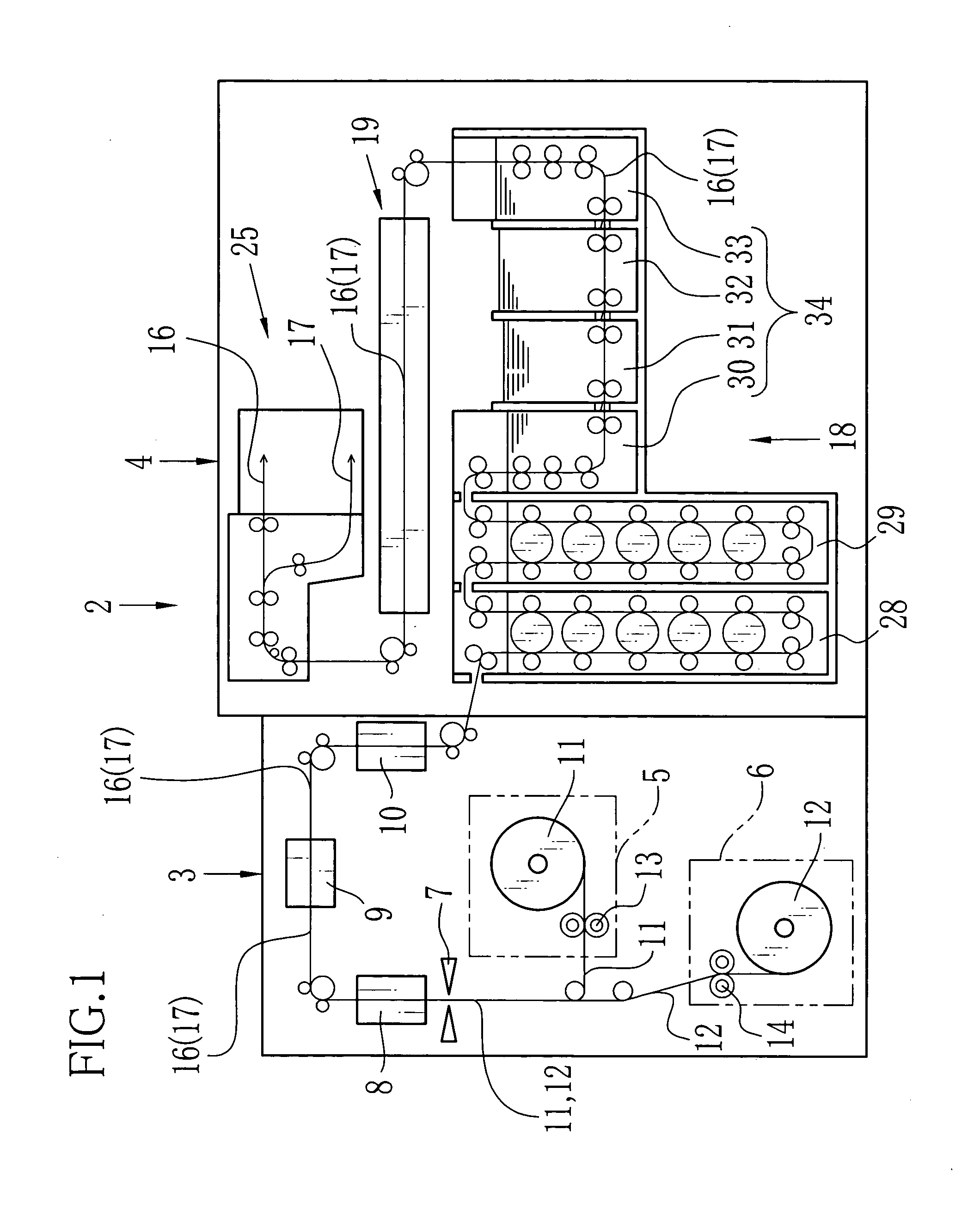
[0032] As shown in FIG. 1, a printer processor 2 is constructed of a printer section 3 and a processor section 4. The printer section 3 is constructed of magazines 5, 6, a cutter 7, a back printer 8, an exposure device 9, and a sheet dispenser 10. The magazines 5, 6 respectively contain rolls of color photographic papers (hereinafter, papers) 11, 12 having different width. When a feed roller 13 rotates, the paper 11 is drawn from the magazine 5, and the cutter 7 cuts the paper 11 in accordance with a print size to obtain a cut sheet paper, for example, an L-size sheet (width 89 mm.times.length 127 mm), a 2L-size sheet (width 127 mm.times.length 178 mm). When a feed roller 14 rotates, the paper 12 is drawn from the magazine 6, and the cutter 7 cuts the paper 12 in accordance with a print size to obtain the cut sheet paper, for example, an A4-size sheet (width 210 mm.times.length 297 mm). Usually, when an order of the printing is made in the photofinisher, one of the print sizes of th...


PUM

PropertyMeasurementUnit
Weightaaaaaaaaaa
Speedaaaaaaaaaa
Shapeaaaaaaaaaa

Abstract

Plural conveying roller pairs are disposed on a conveying path, and plural sheets arranged zigzag are conveyed upwards. At an exit of the conveying path is disposed a movable guide plate to whose forward end a push roller is attached. The movable guide plate is in a horizontal state while the push roller contacts to the drive roller. The sheet in being conveyed upward by a last conveying roller pushes up the movable guide plate. When a rear end of the sheet passes-the last conveying roller, the movable guide plate moves back by its own weight. The sheet is discharged from the conveying path at high speed by the push roller and the drive roller.

Description

[0001] 1. Field of the Invention[0002] The present invention relates to a sheet discharging apparatus used in a printer processor, an automatic development system, an image recording equipment and the like, and particularly to a sheet discharging apparatus for discharging recording sheets arranged in zigzag among rows so as to align in one row.[0003] 2. Description Related to the Prior Art[0004] In a printer processor used in a photolaboratory is used a paper roll in which a continuous photosensitive recording paper is rolled. The photosensitive recording paper which is advanced from the paper roll is cut into recording sheets, and each recording paper is exposed so as to form an image. In the printer processor, thereafter, the recording sheet is conveyed to a development device in which the development and the fixation are made and a dryer in which the drying is made. As the recording sheet, there are a photosensitive recording sheet, normal paper sheet, and the like. And the recor...

Claims


Application Information

Patent Timeline
IPC IPC(8): B65H5/06B65H29/14G03D15/00B65H29/20B65H29/70
CPCB65H29/14B65H2301/51214B65H2801/03B65H2404/1441B65H2404/143
Inventor TANABE, TSUYOSHI
Owner FUJIFILM CORP
Why Eureka
Try Eureka