

Air conditioner for vehicle use
a technology for air conditioners and vehicles, applied in the direction of defrosting, domestic cooling devices, instruments, etc., can solve the problems of increasing the size of the air conditioner (the air conditioner casing), increasing the manufacturing cost of the air conditioner, and unable to give passengers unpleasant feelings
- Summary
- Abstract
- Description
- Claims
- Application Information
AI Technical Summary
Benefits of technology
Problems solved by technology
Method used
Image

Examples
first embodiment
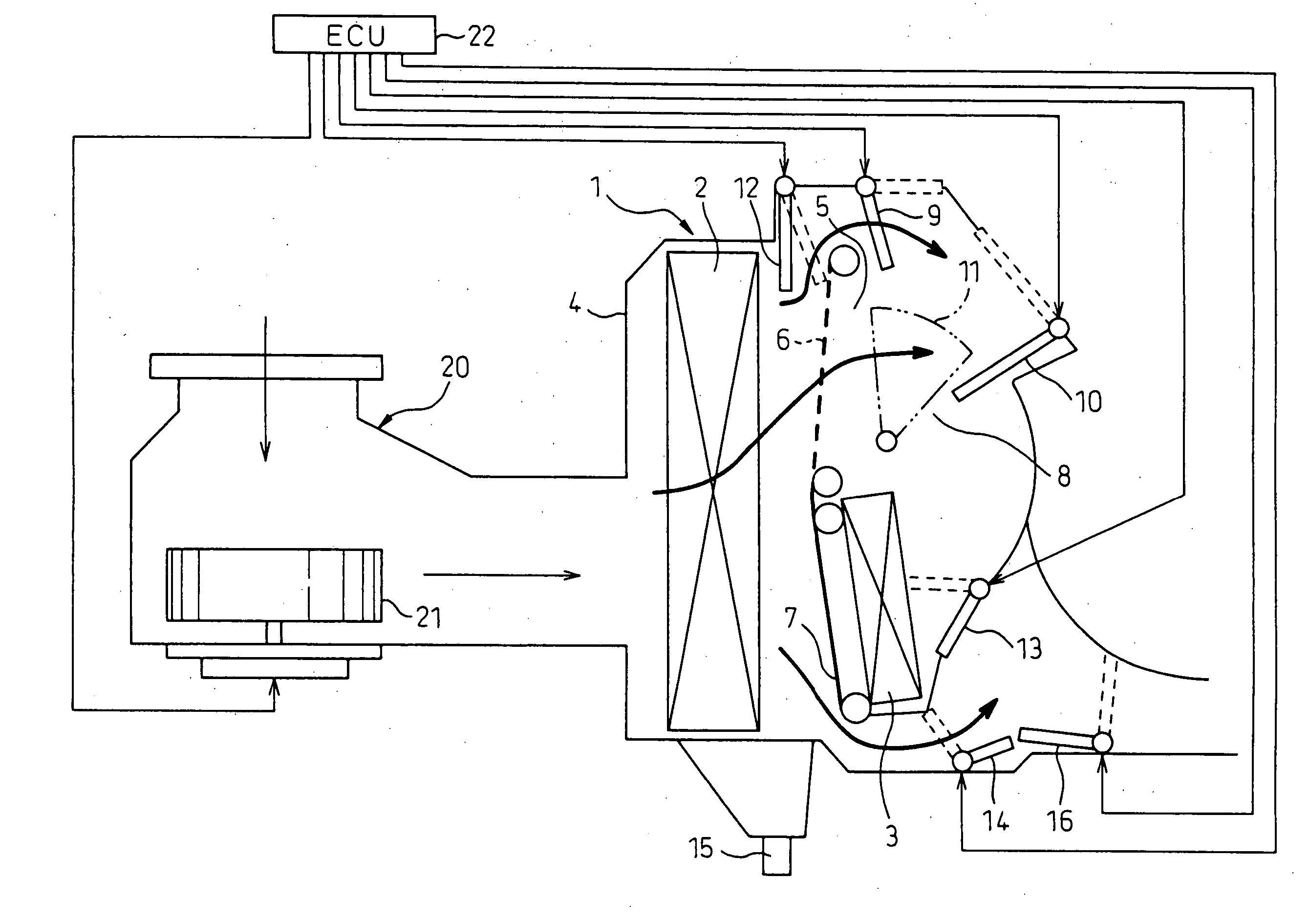
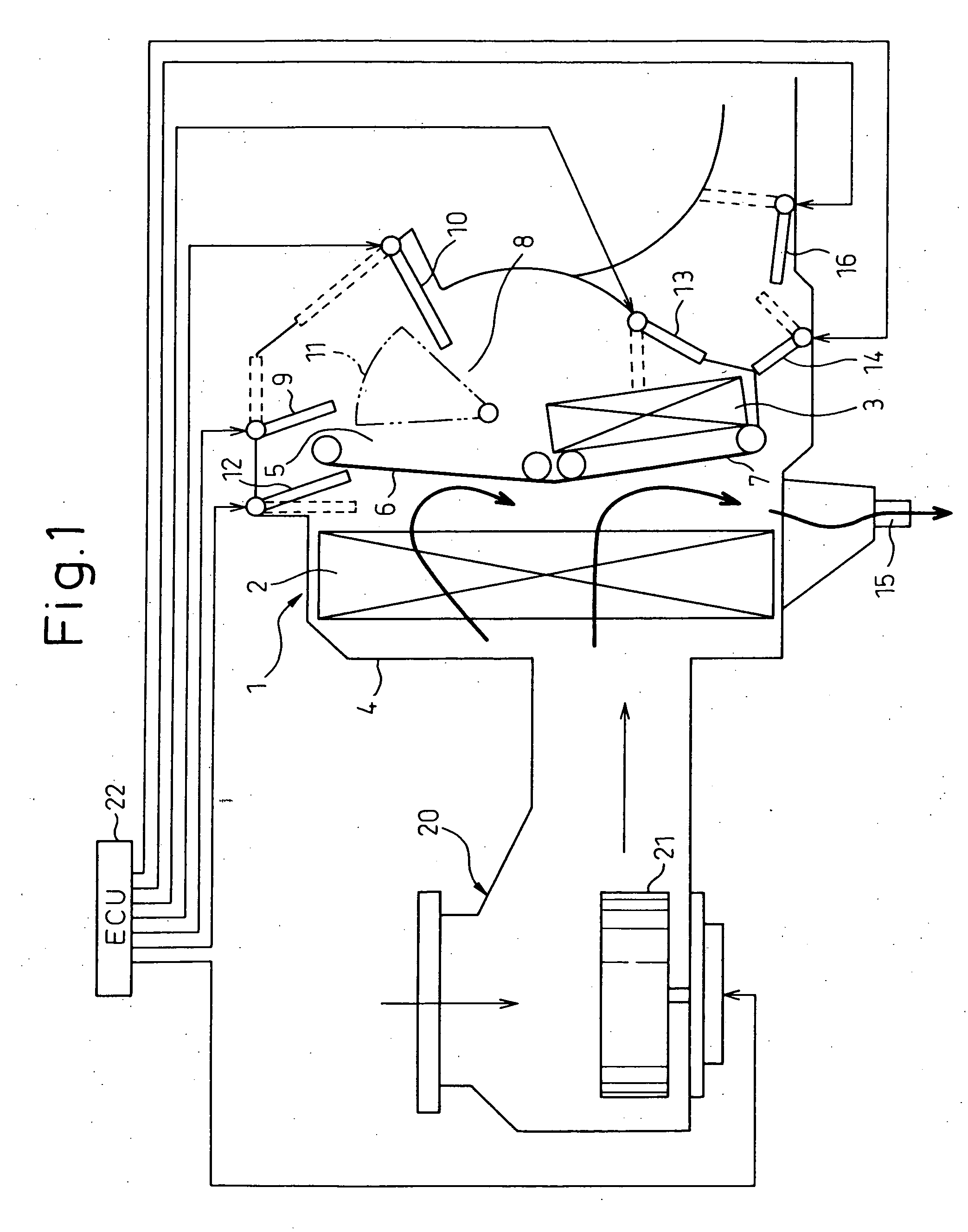
[0048] First, an air conditioner for vehicle use of the present invention will be explained below. FIG. 1 is a view showing a model of the air conditioner for vehicle use of the embodiment of the present invention. This air conditioner for vehicle use includes an air conditioner unit 1 and an air blowing unit 20.
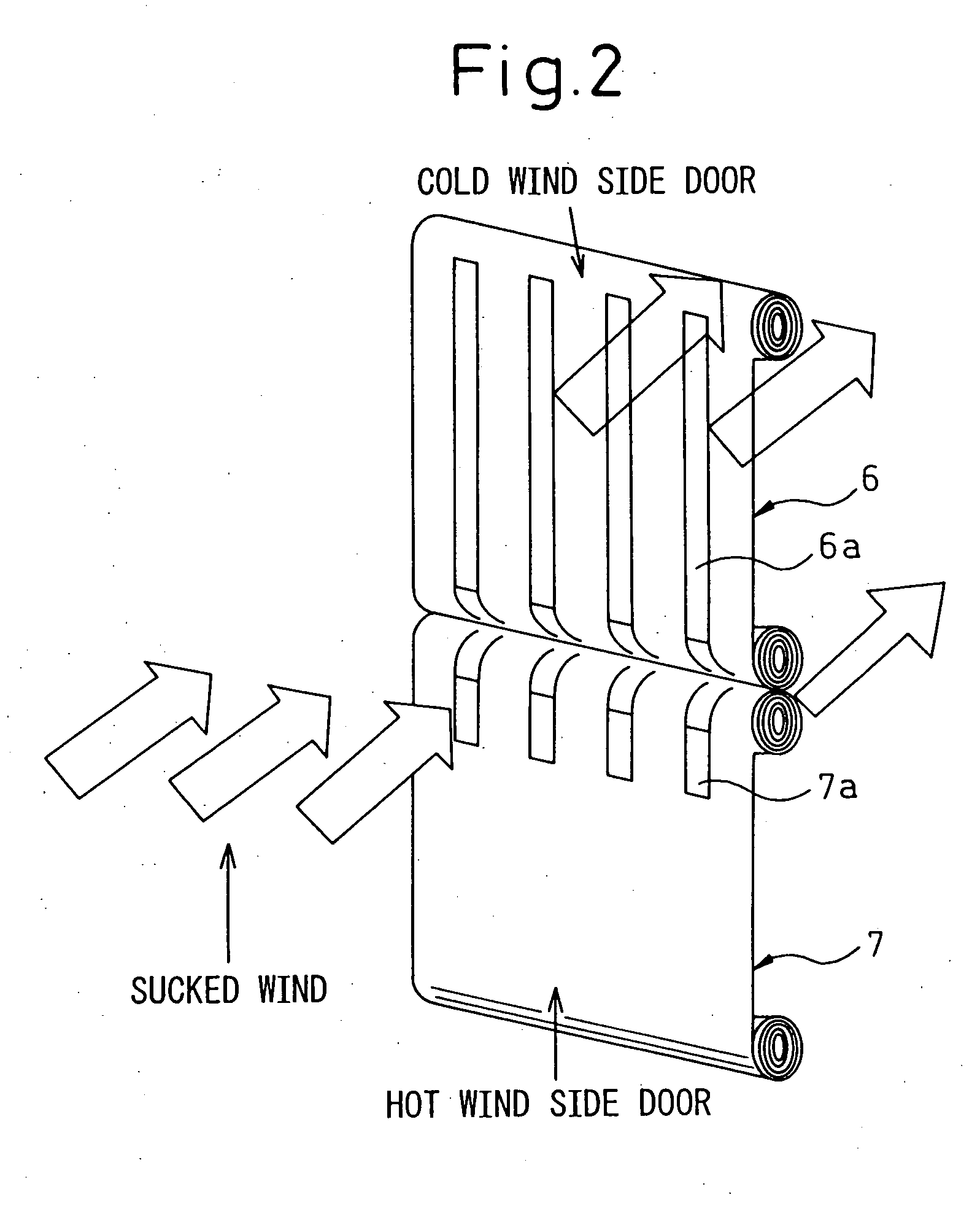
[0049] In this connection, FIG. 2 is a schematic illustration for explaining an air mixing door. FIGS. 3 to 9 are views showing a model of the air current in the air conditioner for vehicle use of this embodiment.
[0050] In FIG. 1, the air blowing unit 20 includes: a blower 21 for blowing air to the air conditioning unit 1; and an inside and outside cooling air changeover device (not shown) for adjusting quantities of inside and outside air supplied to the blower 21.
[0051] The air conditioning unit 1 is composed of an air conditioning casing 4 in which the cooler 2 and the heater 3 are accommodated, and the air passages are composed. In this structure, the cooler 2 is a heat ...
second embodiment
[0081] Next, the second embodiment will be explained below. This embodiment is applied to a vehicle having an automatic ventilating device or an automatic ventilating function in which sensors (not shown) for detecting parameters, which increase according to an increase in the compartment temperature, such as a detection value of the compartment temperature sensor, a detection value of the sunshine sensor and a detection value of the infrared ray sensor, are arranged and when the detection values of these sensors exceed a predetermined value, the passenger compartment is automatically ventilated.
[0082] In this connection, the automatic ventilating device or the automatic ventilating function of the present embodiment is an automatic ventilating means for conducting ventilation in the passenger compartment by automatically operating the air blowing unit 20, that is, by automatically operating the blower 21 in the outside air introducing mode when the detection values of the above sen...
fourth embodiment
[0100] Next, the fourth embodiment will be explained below. In the above embodiment, blowout of the offensive smell components is prevented by drying the cooler 2 before the air conditioner for vehicle use is set in motion. However, in this embodiment, the operation is conducted as follows. Before the air conditioner for vehicle use is set in motion, in the blowing mode in which the cold wind side air mixing door 6, the hot wind side air mixing door 7, the cold wind door 12 and the rear cold wind side air mixing door 14 are totally closed, the compressor, that is, the vapor compression type refrigerating machine is operated and the refrigerating capacity (the air conditioning capacity) is generated in the cooler 2 so that the temperature of the cooler 2 can be lowered, and when the surface of the cooler 2 gets wet so that the offensive smell components cannot be emitted from the surface of the cooler 2, the above blowout mode is released and an air conditioned wind is blown out into...
PUM
 Abstract
Description
Claims
Application Information