Micro-tensile testing system

a micro-tensile and testing system technology, applied in the field of systems and apparatuses, can solve the problems of increasing measurement errors, prior art testing systems and techniques are not suitable for testing extremely small test samples, and are not suitable for large test samples

Inactive Publication Date: 2004-10-14
HONEYWELL FED MFG & TECHNOLOGI
View PDF6 Cites 11 Cited by
  • Summary
  • Abstract
  • Description
  • Claims
  • Application Information

AI Technical Summary

Problems solved by technology

Unfortunately, these prior art testing systems and techniques, while suitable for testing larger test samples, are unsuitable for testing extremely small test samples, such as, for example, test samples of materials engineered using a lithographic electroplating formation (LiGA) process.
Prior art testing systems are often unable to accommodate and secure test samples smaller than approximately 0.030 inch, particularly when substantial force is applied to the test sample during testing.
Furthermore, the frames or structural support members of prior art testing systems often suffer from substantial deflection or bending during testing, particularly under high loading, which can result in increased measurement errors.
Unfortunately, while suitable for use with larger test samples, tangible extensometers can significantly distort test results when used with smaller test samples.
Additionally, prior art testing systems often require substantial labor-intensive work by the user in the form of calibration, test control, data acquisition, and data manipulation and analysis, all of which can substantially increase error risks.

Method used


Image

  • Micro-tensile testing system
  • Micro-tensile testing system
  • Micro-tensile testing system

Examples


Embodiment Construction

, below.

[0021] A preferred embodiment of the present invention is described in detail below with reference to the attached drawing figures, wherein:

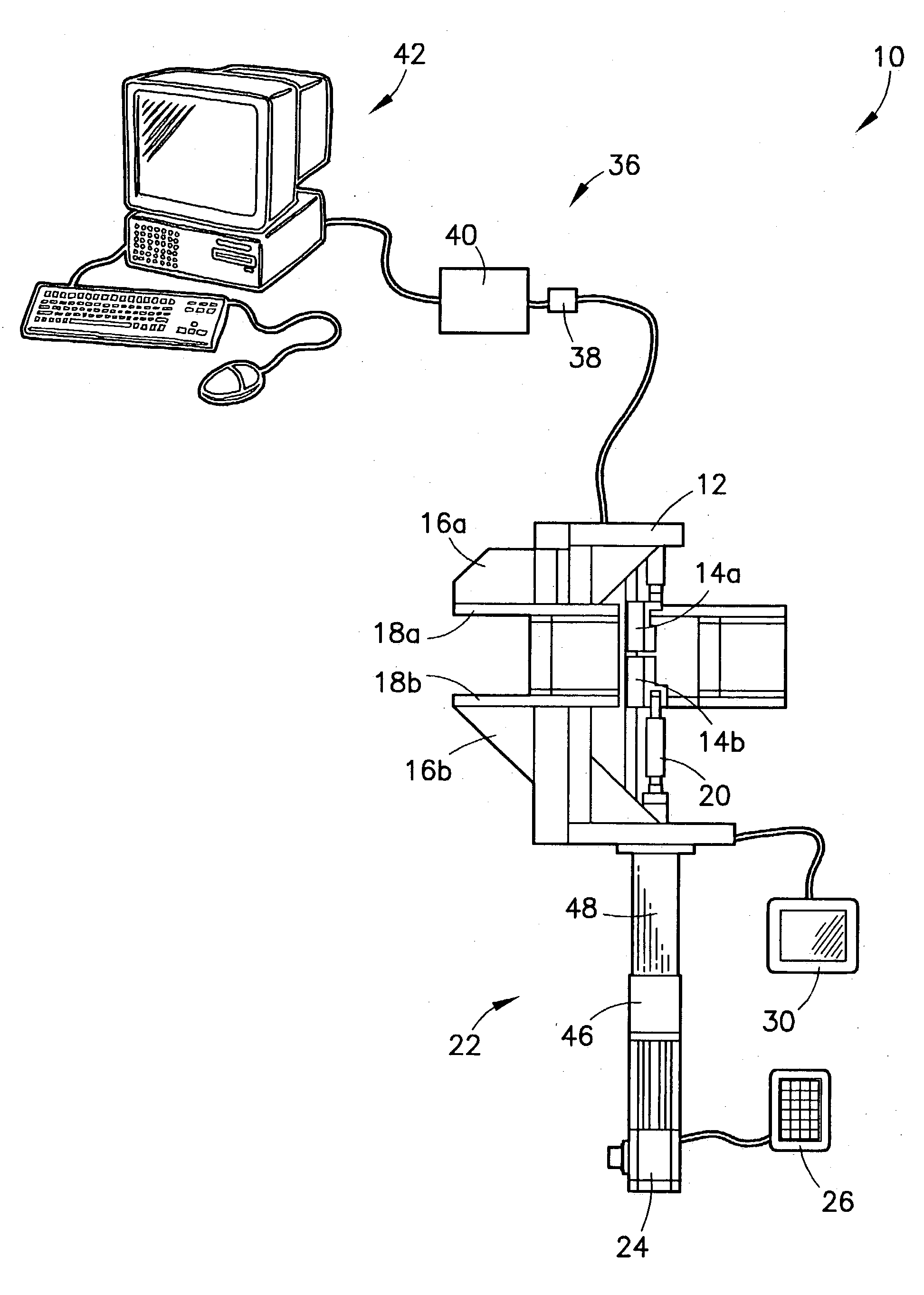
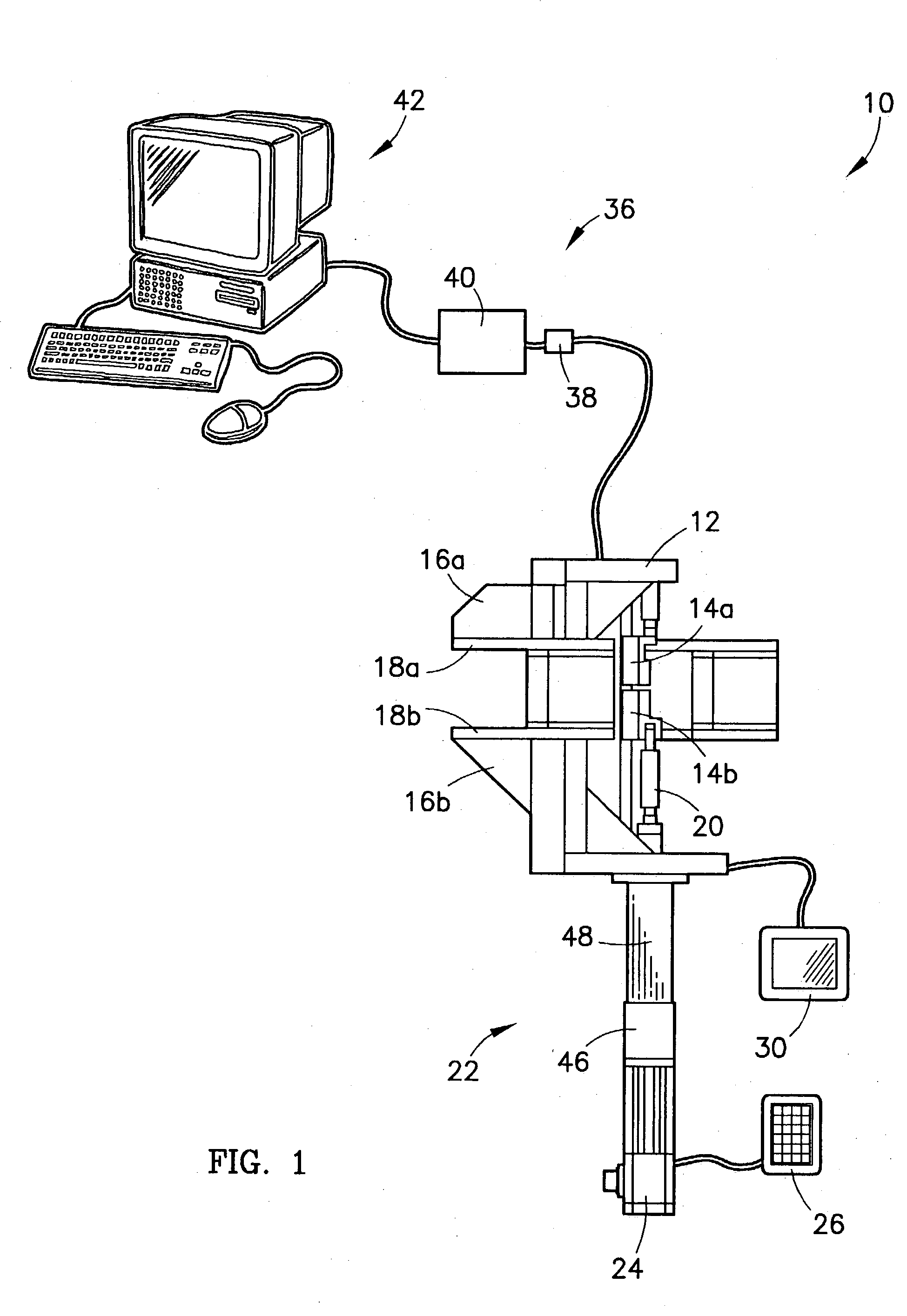
[0022] FIG. 1 is a right side elevational view of a preferred embodiment of a testing system of the present invention;

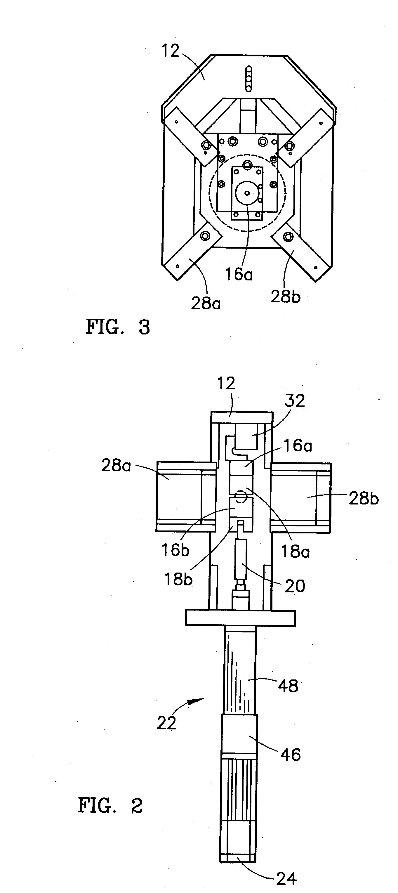
[0023] FIG. 2 is a front elevational view of the testing system of FIG. 1;

[0024] FIG. 3 is a plan view of the testing system of FIG. 1;

[0025] FIG. 4 is a fragmentary view of a portion of the testing system of FIG. 1 magnified to better show gripping support and serrated grip components;

[0026] FIG. 5 is a block diagram showing an exemplary computer program that controls a data acquisition portion of a testing process performed using the testing system of FIG. 1;

[0027] FIG. 6 is a detailed graphical depiction of a measurement portion of the computer program of FIG. 5; and

[0028] FIG. 7 is a screen display of a computer-generated user interface for controlling the testing process.

DETAILED DESCRIPTION OF A PREFERRED EMBODIMENT...


PUM

PropertyMeasurementUnit
thicknessaaaaaaaaaa
thicknessaaaaaaaaaa
thicknessesaaaaaaaaaa

Abstract

A micro-tensile testing system providing a stand-alone test platform for testing and reporting physical or engineering properties of test samples of materials having thicknesses of approximately between 0.002 inch and 0.030 inch, including, for example, LiGA engineered materials. The testing system is able to perform a variety of static, dynamic, and cyclic tests. The testing system includes a rigid frame and adjustable gripping supports to minimize measurement errors due to deflection or bending under load; serrated grips for securing the extremely small test sample; high-speed laser scan micrometers for obtaining accurate results; and test software for controlling the testing procedure and reporting results.

Description

[0002] 1. Field of the Invention[0003] The present invention relates broadly to systems and apparatuses for measuring, determining, or otherwise testing physical or engineering properties of materials. More particularly, the present invention concerns a micro-tensile testing system providing a stand-alone test platform for testing and reporting physical or engineering properties of test samples of materials having thicknesses of approximately between 0.002 inch and 0.030 inch, including, for example, LiGA engineered materials, wherein the testing system is able to perform a variety of static, dynamic, and cyclic tests, and includes serrated grips for securing the test sample, dual high-speed laser scan micrometers for obtaining accurate results, and test software for controlling the testing procedure and reporting results.[0004] 2. Description of the Prior Art[0005] It is often desirable to measure, determine, or otherwise test physical or engineering properties of test samples of m...

Claims


Application Information

Patent Timeline
Patent Type & Authority Applications(United States)
IPC IPC(8): G01L1/24G01N3/00G01N3/02G01N3/06
CPCG01N3/02G01N2203/0016G01N2203/0021G01N2203/0023G01N2203/0286G01N2203/0647G01N2203/0682
Inventor WENSKI, EDWARD G.
Owner HONEYWELL FED MFG & TECHNOLOGI
Why Eureka
Try Eureka