Signal to noise ratio measurement in a communications system

a communication system and signal to noise ratio technology, applied in transmission monitoring/testing/fault-measurement systems, electromagnetic transmission, transmission, etc., can solve the problem of significant overestimation of the osnr of add/drop channels, small differences between the transmission properties of individual wavelengths multiplied, and difficult measurement of optical signal to noise ratio

Inactive Publication Date: 2004-10-21
NORTEL NETWORKS LTD
View PDF4 Cites 5 Cited by
  • Summary
  • Abstract
  • Description
  • Claims
  • Application Information

AI Technical Summary

Benefits of technology

The technical effect of this patent is to reduce or eliminate the disadvantage described earlier.

Problems solved by technology

The technical problem of this patent text is not specified and requires further analysis and interpretation.

Method used


Image

  • Signal to noise ratio measurement in a communications system
  • Signal to noise ratio measurement in a communications system
  • Signal to noise ratio measurement in a communications system

Examples


Embodiment Construction

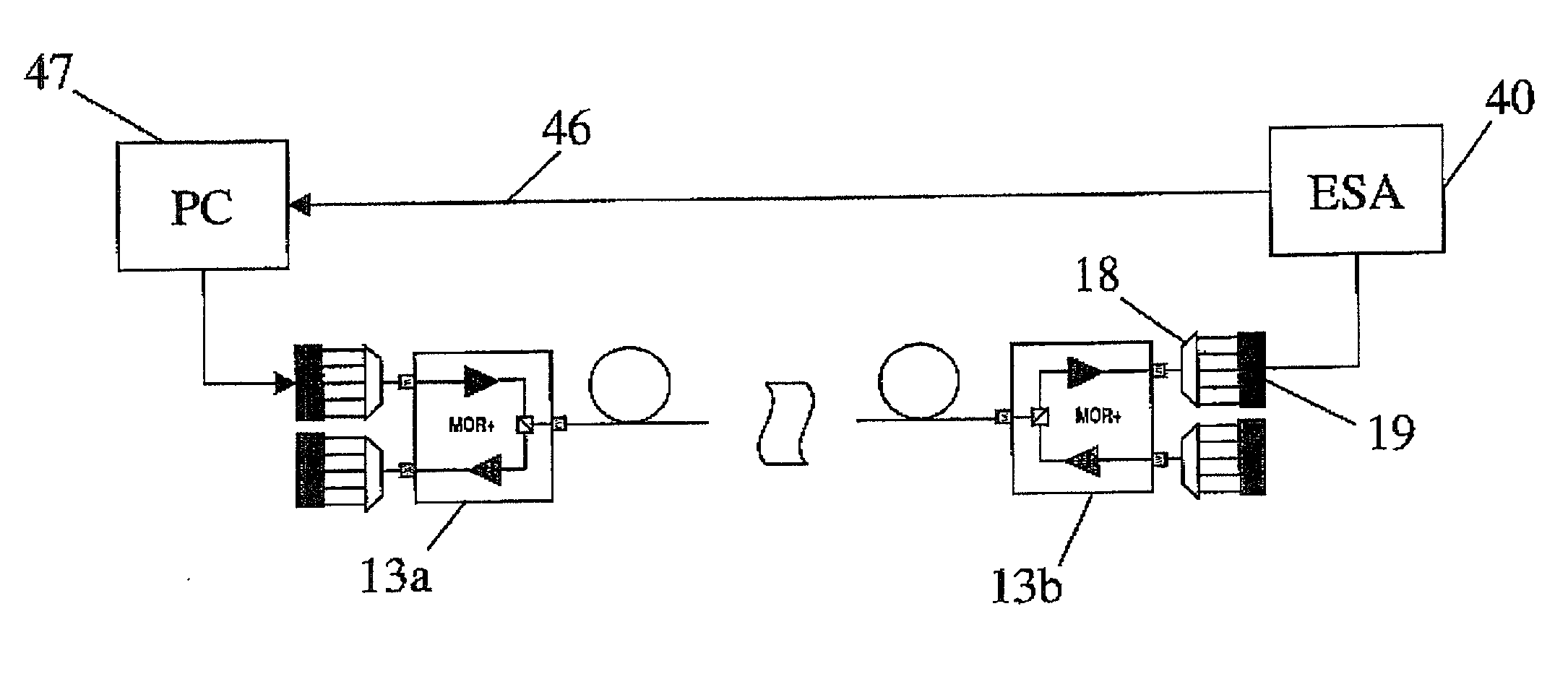
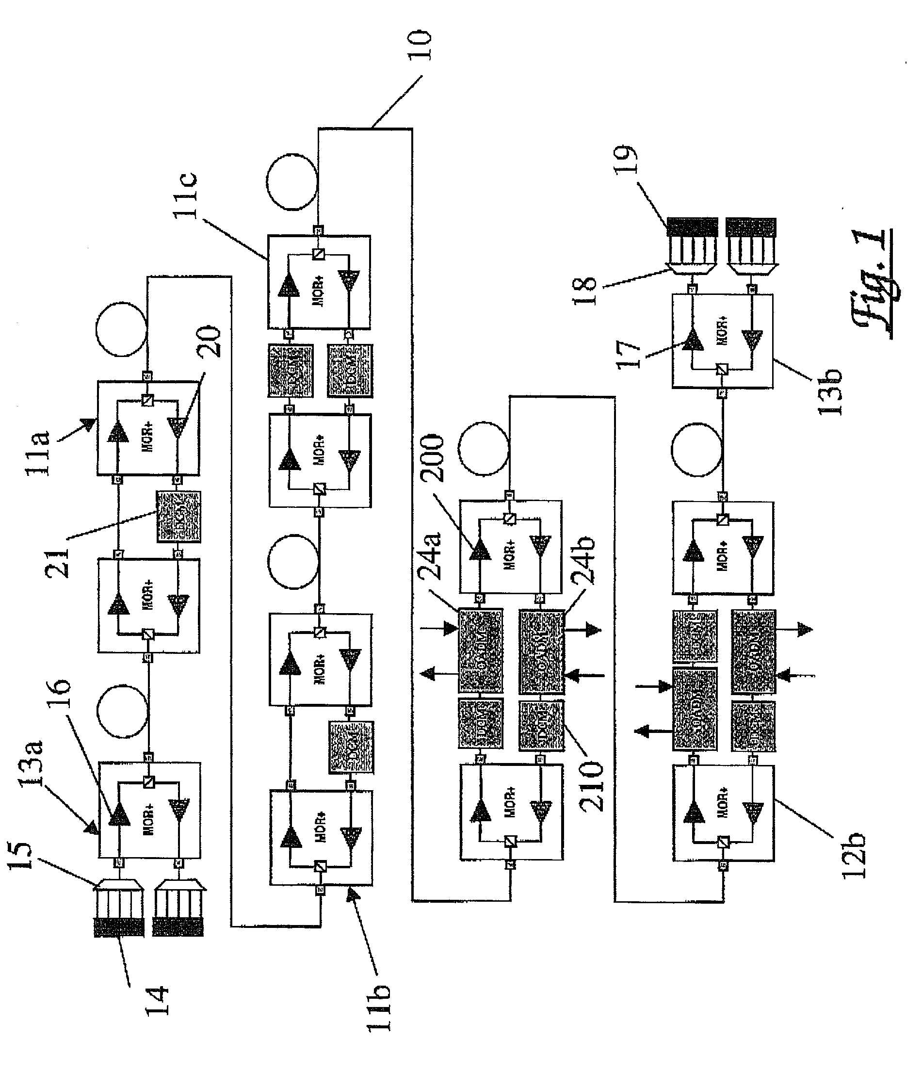
[0026] Referring first to FIG. 1, this shows in schematic form the construction of a multi-wavelength optical regenerator (MOR) fibre transmission system incorporating amplifier sites 11a, 11b, 11c and add / drop sites 12a, 12b disposed between terminal citations 13c, 13b and interconnected by fibre path 10. The system is bi-directional. Thus, each terminal station 13c, 13b incorporates on the transmitter side, a transmitter array 14, an input multiplexer 15 and a transmitter amplifier 16. On the receiver side, the terminal station incorporates a receiver amplifier 17, a receiver demultiplexer 18 and a receiver (photodiode) array 19.

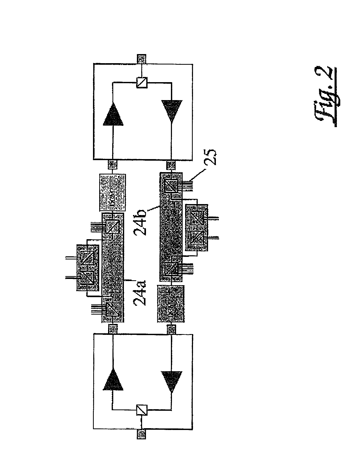
[0027] Each amplifier station incorporates forward and reverse direction amplifiers 20 and one or more dispersion compensation modules 21 for the forward and / or reverse direction paths. Each add / drop site 12a, 12b incorporates forward and reverse direction amplifiers 200, dispersion compensator modules 210 and optical add / drop multiplexers 24a, 24b for the...


PUM


Abstract

The transmission properties of the signal carrier wavelengths in a wavelength division multiplexed optical transmission system are equalised with reference to their signal to noise ratios at a receiver. Each wavelength transmitter transmits a bit sequence as a modulation on the respective wavelength. At the receivers each wavelength modulated with the bit sequence is converted into a corresponding electrical signal. From a spectrum of that electrical signal, an electrical signal to noise ratio is determined. The measurements for the wavelengths are used to control adjustment of the individual wavelength transmitters such that the signal to noise ratios of the wavelengths are substantially equal.

Description


Claims


Application Information

Patent Timeline
Owner NORTEL NETWORKS LTD
Why Eureka
Try Eureka