System and method for using execution contexts in block diagram modeling

a technology of execution context and block diagram, applied in the field of system and method for using execution context in block diagram modeling, can solve the problems of inconvenient use, inefficient and inaccurate, and non-modular design that discourages the use of multiple programming design groups

Active Publication Date: 2004-10-21
THE MATHWORKS INC
View PDF5 Cites 115 Cited by
  • Summary
  • Abstract
  • Description
  • Claims
  • Application Information

AI Technical Summary

Benefits of technology

[0006] The illustrative embodiment of the present invention provides a method of controlling the conditional execution of elements and subsystems in a block diagram. Data structures known as Execution Contexts are created and associated with individual block diagram elements and / or subsystems. The Execution Contexts allow execution of the associated element or subsystem upon satisfaction of a specified pre-condition. The Execution Contexts may be inherited by other elements and subsystems in the block diagram and propagated programmatically throughout the block diagram. The use of the Execution Contexts allows for efficient code generation and block diagram execution, as well as supporting modular design concepts.

Problems solved by technology

Such systems range from simple to highly complex systems.
Unfortunately, the execution of conventional block diagram elements is highly dependent upon sample times (sample rates) of other elements in the block diagram.
For elements which should only be conditionally executed this leads to inaccurate and inefficient results.
Where conditional execution of elements by group in a subsystem is available, it requires the grouping of other non-subsystem elements with the subsystem in order to control execution times. The forced inclusion of elements within a subsystem results in non-modular designs that discourage the use of multiple programming design groups.

Method used


Image

  • System and method for using execution contexts in block diagram modeling
  • System and method for using execution contexts in block diagram modeling
  • System and method for using execution contexts in block diagram modeling

Examples


example revisited

CONDITIONAL INPUT EXAMPLE REVISITED

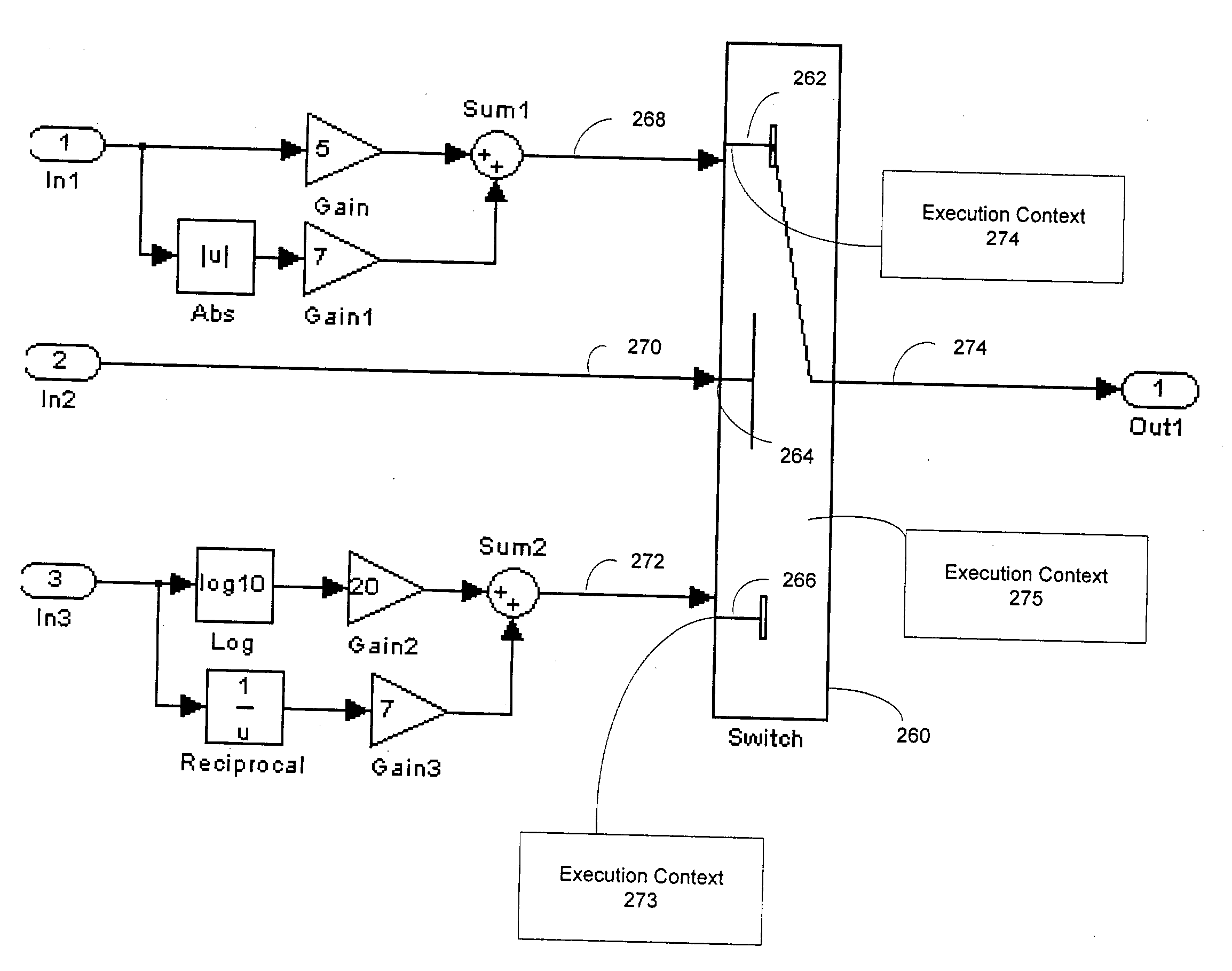
[0222] FIG. 15 showed a block diagram with conditional inputs 262 and 266 for a switch 260. The Sorted Lists for the block diagram before and after the use of Execution Contexts for the block diagram may be shown as follows:

[0223] Sorted List without use of ECs

[0224] In1

[0225] Gain

[0226] Abs

[0227] Gain1

[0228] Sum1

[0229] In2

[0230] In3

[0231] Log

[0232] Gain2

[0233] Reciprocal

[0234] Gain3

[0235] Sum2

[0236] Switch

[0237] Out1

[0238] Sorted List with use of ECs

[0239] In1

[0240] In2

[0241] In3

[0242] Switch

[0243] Sorted List for Input Port 1:

[0244] Gain

[0245] Abs

[0246] Gain1

[0247] Sum1

[0248] Sorted List for Input Port 2:

[0249] Log

[0250] Gain2

[0251] Reciprocal

[0252] Gain3

[0253] Sum2

[0254] Switch Body

[0255] Out1

[0256] It should be noted that when ECs are used, the Sorted List is hierarchical and the Switch block has two Sorted Lists, one each for the ECs it sets up on its input ports. The generated code for the same model before and after the use of ECs may be sho...


PUM


Abstract

A method of controlling the conditional execution of elements and subsystems in a block diagram is disclosed. Data structures known as Execution Contexts are created and associated with individual block diagram elements and subsystems. The Execution Contexts allow execution of the associated element or subsystem upon satisfaction of a specified pre-condition. The Execution Contexts may be inherited by other elements and subsystems in the block diagram and propagated programmatically throughout the block diagram. The use of the Execution Contexts allows for efficient code generation and block diagram execution, as well as supporting modular design concepts.

Description

[0001] The illustrative embodiment of the present invention relates generally to block diagram modeling and more particularly to block diagram modeling using Execution Contexts, a data structure associated with blocks and subsystems of blocks which provides fine-grained control over the execution of the associated elements based on the satisfaction of a pre-condition.[0002] Various classes of block diagrams describe computations that can be performed on application specific computational hardware, such as a computer, microcontroller, FPGA, and custom hardware. Classes of such block diagrams include time-based block diagrams, such as those found within Simulink.RTM. from the MathWorks, Inc., of Natick, Mass., state-based and flow diagrams, such as those found within Stateflow.RTM. from the MathWorks, Inc., of Natick, Mass., and data-flow diagrams. A common characteristic among these various forms of block diagrams is that they define semantics on how to execute the diagram.[0003] His...

Claims


Application Information

Patent Timeline
Patent Type & Authority Applications(United States)
IPC IPC(8): G06F7/00G06F9/40G06F9/44G06F9/45G06F17/00G06F17/50
CPCG06F8/34G06F8/443
Inventor CIOLFI, JOHN EDWARDMANI, RAMAMURTHYOROFINO, DONALD PAULSHAKERI, MOJDEHULLMAN, MARCYEDDANAPUDI, MURALI
Owner THE MATHWORKS INC
Why Eureka
Try Eureka