Hydro turbine generator

Active Publication Date: 2009-01-22
SHIFRIN SALVATORE +1
View PDF61 Cites 31 Cited by
  • Summary
  • Abstract
  • Description
  • Claims
  • Application Information

AI Technical Summary

Problems solved by technology

None of these prior art disclosures provide a specifically designed hydroelectric turbine for use in small, micro or mini-hydro application

Method used


Image

  • Hydro turbine generator
  • Hydro turbine generator
  • Hydro turbine generator

Examples


Embodiment Construction

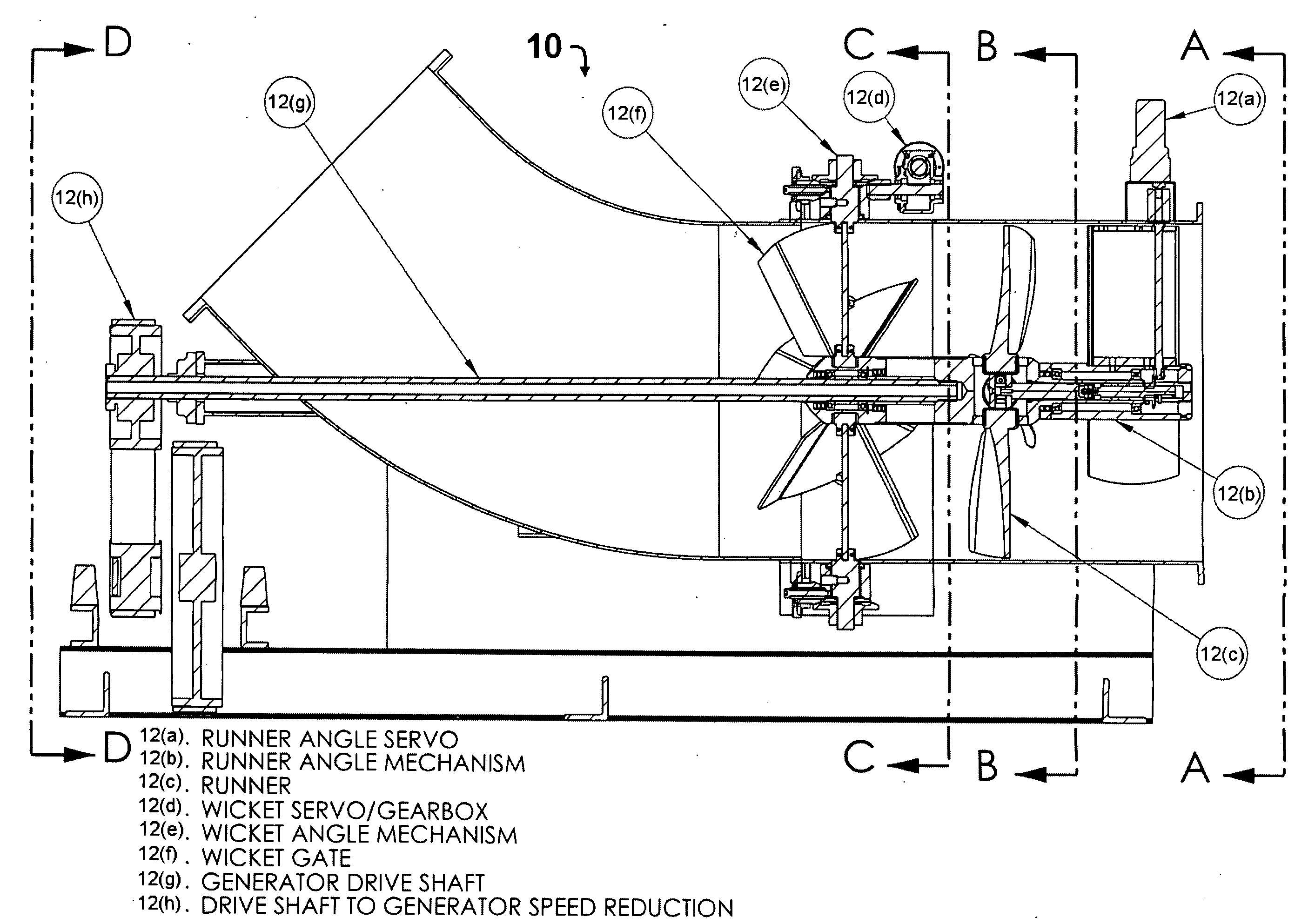
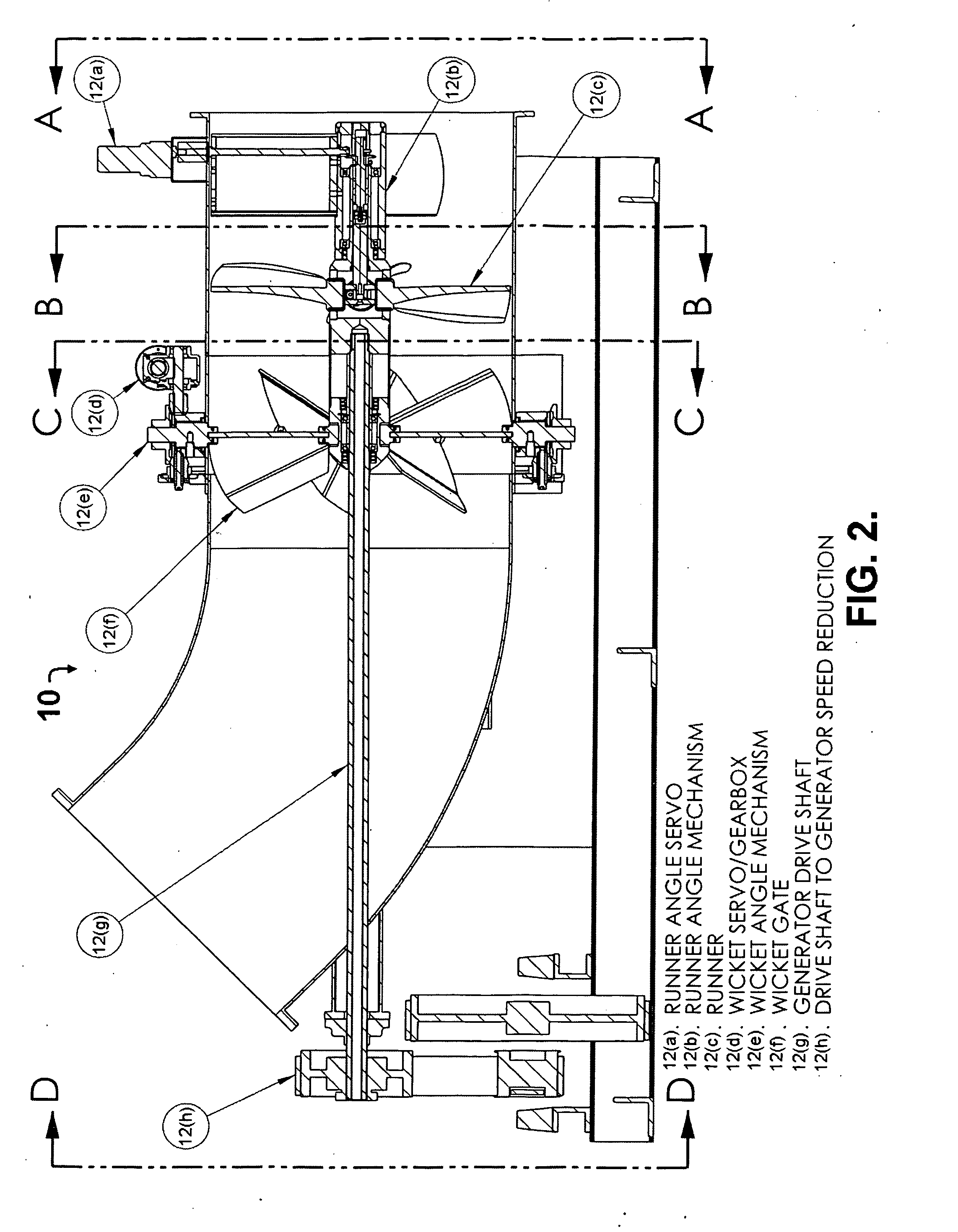
[0013]The present invention is designed for low head, high flow volume sites. The hydroelectric turbine comprises a double regulated propeller and utilizes the Kaplan turbine and gate system to produce electrical power efficiently through a wide range of flows common in “run of the river systems”. The hydroelectric turbine is designed to operate at efficiency levels greater than 90%, and can handle flows as low as 20 cfs. The total unit output flexibility is typically between 100 kw and 700 kw.

[0014]A hydroelectric turbine in accordance with the present invention can run on or off of a power grid; is modular in design, therefore multiple units can be operated in series; has the ability to alternate between the primary turbine and a series of turbines; and comprises a means for automatic recognition and synchronization when using multiple units.

[0015]The present invention comprises an integrated self-contained computer based control system. The closed looped control software modulate...


PUM


Abstract

A hydroelectric turbine generator and control system is provided that optimizes the maximum possible power output at all times by strictly monitoring power output from the generator unit and modulating the wicket gate angle and the runner blade pitch independently of one another. The hydroelectric turbine generator includes a means for separately controlling wicket gate angle and runner blade pitch. The wicket gate angle control mechanism controls the flow into the system, pre conditions flow for maximum power and maintains reservoir level. The runner blade pitch control mechanism continuously monitors the system power output based on actual power produced, and adjusts system parameters in order to achieve maximum power output.

Description

CROSS-REFERENCE TO RELATED APPLICATION[0001]This application claims the benefit of U.S. Provisional Application No. 60 / 958,368 filed Jul. 05, 2007.BACKGROUND OF THE INVENTION[0002]1. Field of the Invention[0003]The present invention generally relates to a system and apparatus for generating electrical power. More specifically, this invention is directed to a hydroelectric turbine generator and computer based control system. The hydroelectric turbine generator can be installed and operated in low head, high volume “run of the river” hydroelectric sites throughout the world.[0004]The hydroelectric turbine is specifically designed for small hydro applications and is not a “scaled down” larger turbine. The hydroelectric turbine takes advantage of the current state of the art technology, and applies it in the most appropriate manner for currently underutilized small hydro power sites. In Connecticut, Massachusetts and New York alone, there are 4,100 registered dams. Of these registered d...

Claims


Application Information

Patent Timeline
IPC IPC(8): F03B15/16F03B13/10
CPCF03B3/06F03B3/183F03B13/10Y02E10/226F05B2270/706Y02E10/22Y02E10/223F03B15/16F03B15/14Y02E10/20
Inventor SHIFRIN, SALVATORESHIFRIN, JOSEPH
Owner SHIFRIN SALVATORE
Why Eureka
Try Eureka