Cutter, cutting method, apparatus for producing interlabial pad, and method for producing the same
a cutting method and interlabial pad technology, applied in the direction of bottle/container closure, transportation and packaging, liquid handling, etc., can solve the problems of dislocation of sanitary products, uniform or ununiform thickness of base materials,
- Summary
- Abstract
- Description
- Claims
- Application Information
AI Technical Summary
Benefits of technology
Problems solved by technology
Method used
Image

Examples
first embodiment
[0072] First Embodiment
[0073] Structure of an Apparatus for Producing Interlabial Pad
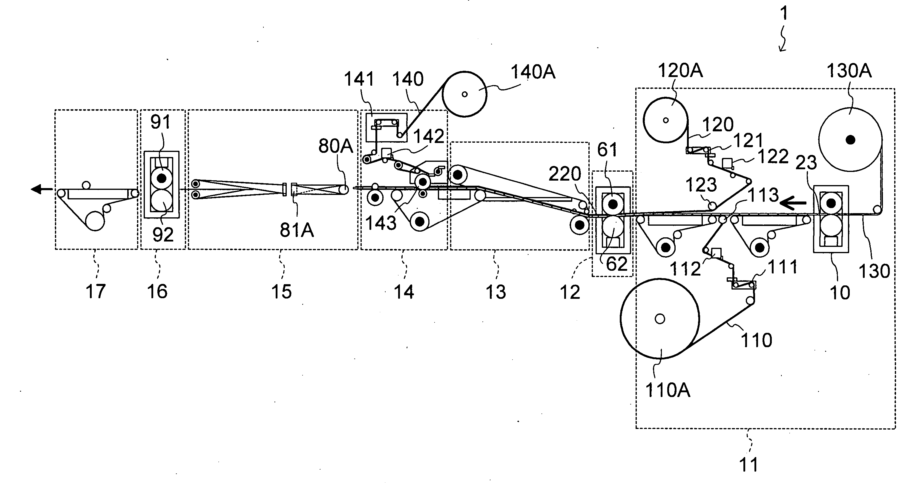
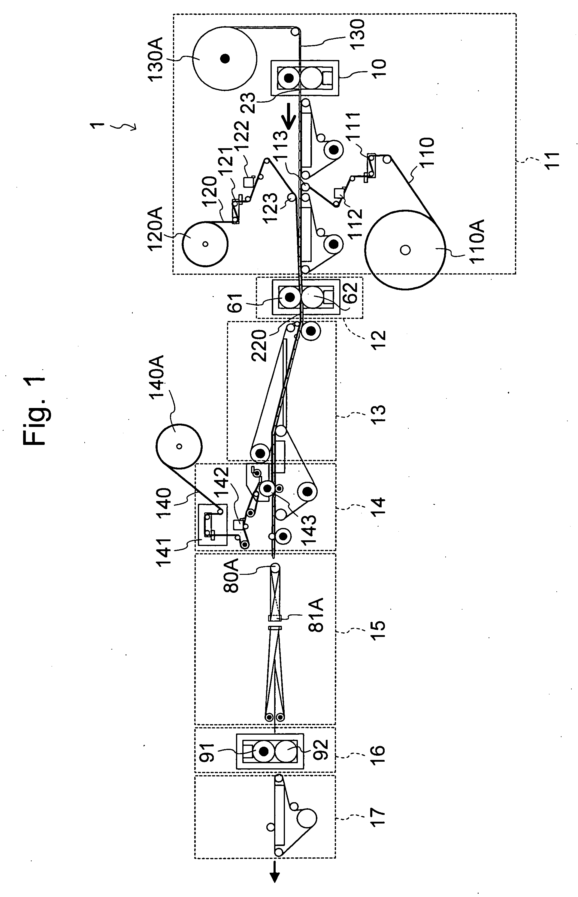
[0074] FIG. 1 shows an apparatus for producing an interlabial pad comprising a cutter according to the first embodiment of the present invention.
[0075] An interlabial pad producing apparatus 1 includes a raw material supplier 11, a bonding-fixing unit 12, a protruded-area forming unit 13, a mini-sheet piece attaching unit 14, a folding unit 15, a cutting unit 16, and a product conveyer 17.
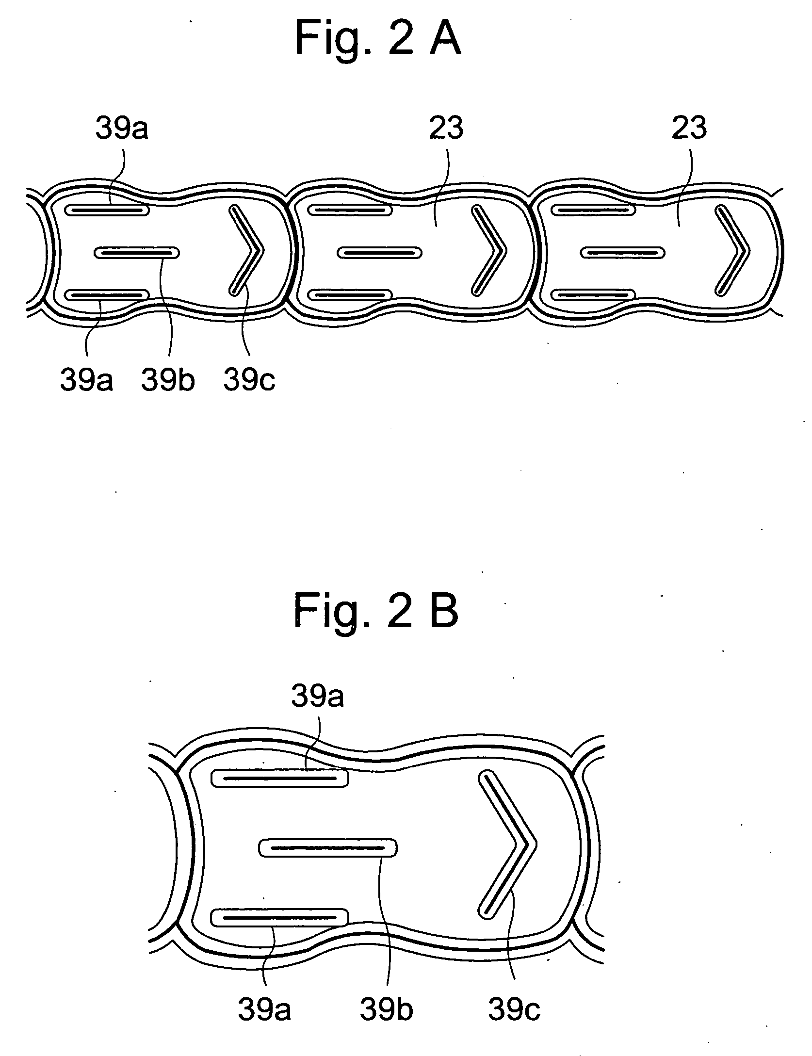
[0076] In the raw material supplier 11, a continuous base material 130 wound on a raw material roller 130A is fed from the raw material roller 130A to a cutter 10. In the cutter 10, absorbent bodies 23 are cut out from the continuous base material 130 (see FIG. 2A), and the absorbent bodies 23 are transferred in the arrow direction. The cutter 10 will be described later.
[0077] As shown in FIG. 2A and FIG. 2B, four slits 39a, 39b, 39c are formed in the absorbent body 23 by the cutter 10. The center slit 39b is forme...
second embodiment
[0112] Second Embodiment
[0113] FIG. 6 shows the cut pattern of a cutter according to the second embodiment of the present invention. The embodiment differs from the first embodiment in respect of the cut pattern formed from the absorbent bodies 23 continuously on the continuous base material 130.
[0114] With the embodiment, the amount of the trim taken up in trim absorbent bodies 134a, 134c can be decreased.
third embodiment
[0122] Third Embodiment
[0123] FIG. 9 and FIG. 10 show a cutter 10C according to the third embodiment of the present invention.
[0124] The embodiment differs from the first embodiment in respect that it includes an embossing device 41 and a slit forming device 51.
[0125] The cutter 10C includes the cutting mechanism 21, the transporting conveyer 22, and the base material remainder discharging mechanism 24. The cutter 10C further includes the embossing device 41 and the slit forming device 51 as a cutting plane line forming means. The embossing device 41 is provided along the line X-X' shown in FIG. 10, the slit forming device 51 is provided along the line Y-Y' shown in FIG. 10, and the cutting mechanism 21 is provided along the line Z-Z'.
[0126] In the embodiment, the continuous base material 130 is fed by the sheet fabric supplier 31. The sheet fabric supplier 31 is for forming the continuous base material 130 and includes a spool 38 on which a sheet fabric 37 for the absorbent body is...
PUM
| Property | Measurement | Unit |
|---|---|---|
| angle | aaaaa | aaaaa |
| length | aaaaa | aaaaa |
| speed | aaaaa | aaaaa |
Abstract
Description
Claims
Application Information
 - R&D
- Intellectual Property
- Life Sciences
- Materials
- Tech Scout
- Unparalleled Data Quality
- Higher Quality Content
- 60% Fewer Hallucinations
Browse by: Latest US Patents, China's latest patents, Technical Efficacy Thesaurus, Application Domain, Technology Topic, Popular Technical Reports.
© 2025 PatSnap. All rights reserved.Legal|Privacy policy|Modern Slavery Act Transparency Statement|Sitemap|About US| Contact US: help@patsnap.com