Battery power circuit and automobile battery power circuit

a battery power circuit and battery technology, applied in the direction of electric variable regulation, process and machine control, instruments, etc., can solve the problems of power circuits being expensive, power conversion circuits 5 becoming expensive, and further increasing costs

Inactive Publication Date: 2004-11-11
MITSUBISHI ELECTRIC CORP
View PDF2 Cites 55 Cited by
  • Summary
  • Abstract
  • Description
  • Claims
  • Application Information

AI Technical Summary

Benefits of technology

[0017] In addition, a control unit may be provided for making control to prevent the first switch and the second switch from being turned on simultaneously.

Problems solved by technology

Thus, even if a battery group having a rated voltage of 36 V is provided for attaining the idle stop operation, the power circuit will be expensive because the high-capacity DC / DC converter 300 or the high-capacity stationary battery 100 is required.
Since the high-capacity DC / DC converter 300 generates a great deal of heat, accessories for cooling are required to thereby cause further increase in cost.
Thus, the power conversion circuit 5 becomes expensive.
However, at the time of initial start-up in such a configuration, it is necessary to supply a large quantity of charges to the cell motor.
This causes a great obstacle to reduction in cost.
Accessories associated with the DC / DC converter are expensive, and the high-capacity 12V stationary battery 100 is also expensive and becomes an obstacle to miniaturization.

Method used


Image

  • Battery power circuit and automobile battery power circuit
  • Battery power circuit and automobile battery power circuit
  • Battery power circuit and automobile battery power circuit

Examples


embodiment 1

[0039] (Embodiment 1)

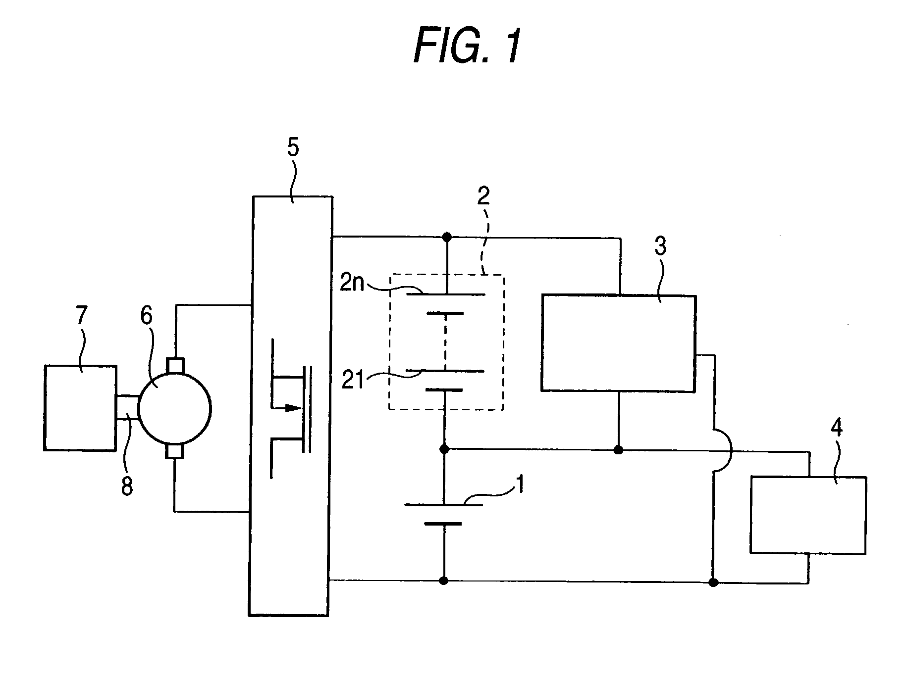
[0040] FIG. 1 shows the configuration of an automobile battery power circuit according to Embodiment 1 of the invention. A battery group 1 (first battery group) and a battery group 2 (second battery group) are connected in series. The reference numeral 3 represents a DC / DC converter inserted between the battery group 1 and the battery group 2; 4, a load connected to the battery group 1; 5, a power conversion circuit connected to the opposite ends of the series body of the battery group 1 and the battery group 2; 6, an electric motor connected to the power conversion circuit 5; 7, an engine; and 8, a power transmitter for transmitting power between the electric motor 6 and the engine 7. Here, for example, the battery group 1 is constituted by one battery having a rated voltage of 12 V, and the battery group 2 is constituted by n batteries having a rated voltage of 12 V, that is, batteries 21 to 2n. The DC / DC converter 3 is connected among the opposite ends of the...

embodiment 2

[0044] (Embodiment 2)

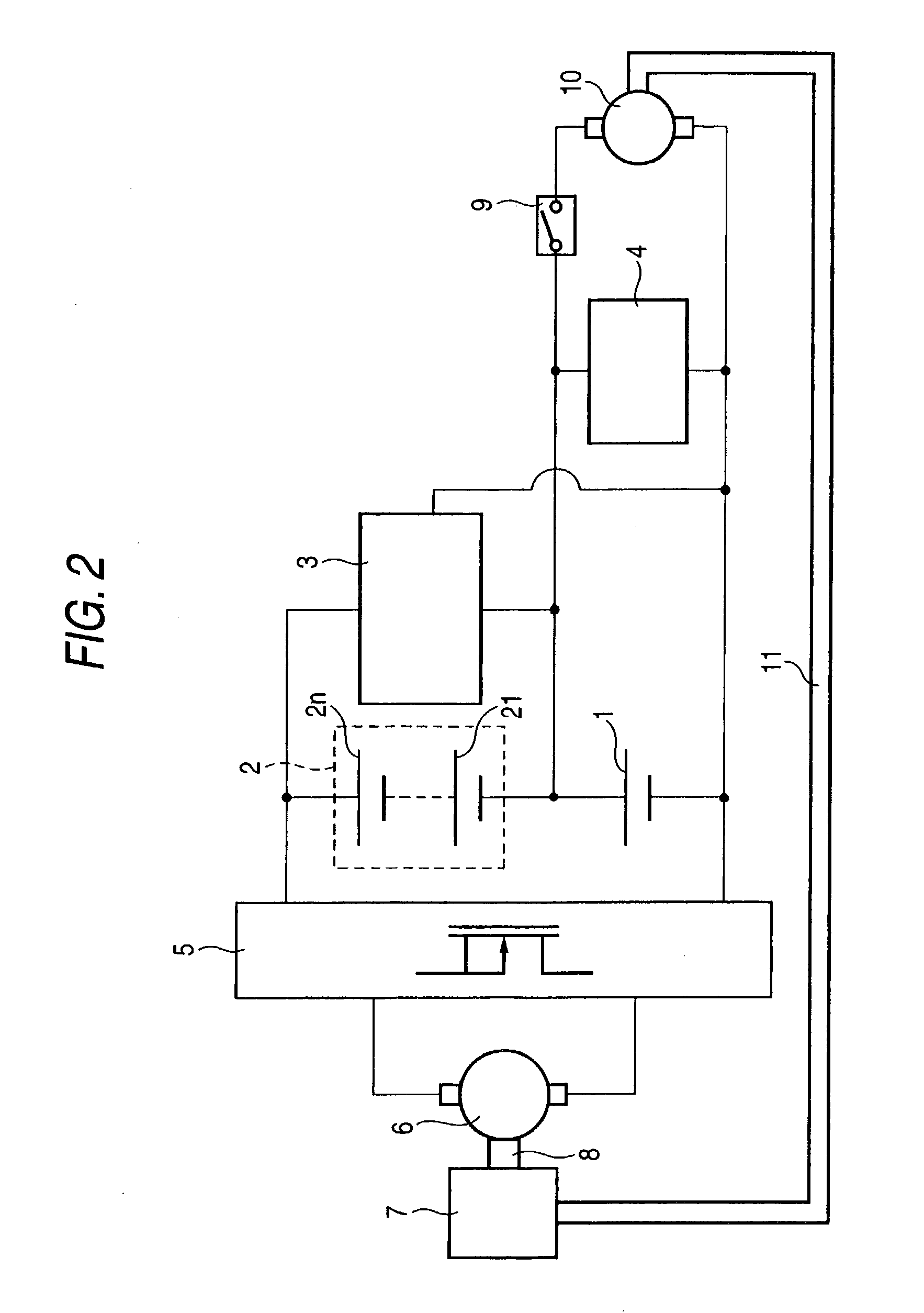
[0045] FIG. 2 shows the configuration of an automobile battery power circuit according to Embodiment 2 of the invention. The automobile battery power circuit in FIG. 2 is different from that in FIG. 1 in that a cell motor 10 is connected to the battery group 1 through a key switch 9 for initial start-up. Only the initial start-up requiring high power is performed by the cell motor 10. As a result, electric power is supplied to the electric motor 6 through the power conversion circuit 5 so as to start the engine 7 only when the engine 7 is warmed up, so that the capacity of the power conversion circuit 5 can be reduced as described in the related art. A cell motor power transmitter 11 is used to start the engine 7 by means of the cell motor 10. In order to lead the engine 7 to a predetermined number of revolutions by means of the limited power of the cell motor 10, torque conversion may be performed using a belt, gears, or the like, in the cell motor power transm...

embodiment 3

[0046] (Embodiment 3)

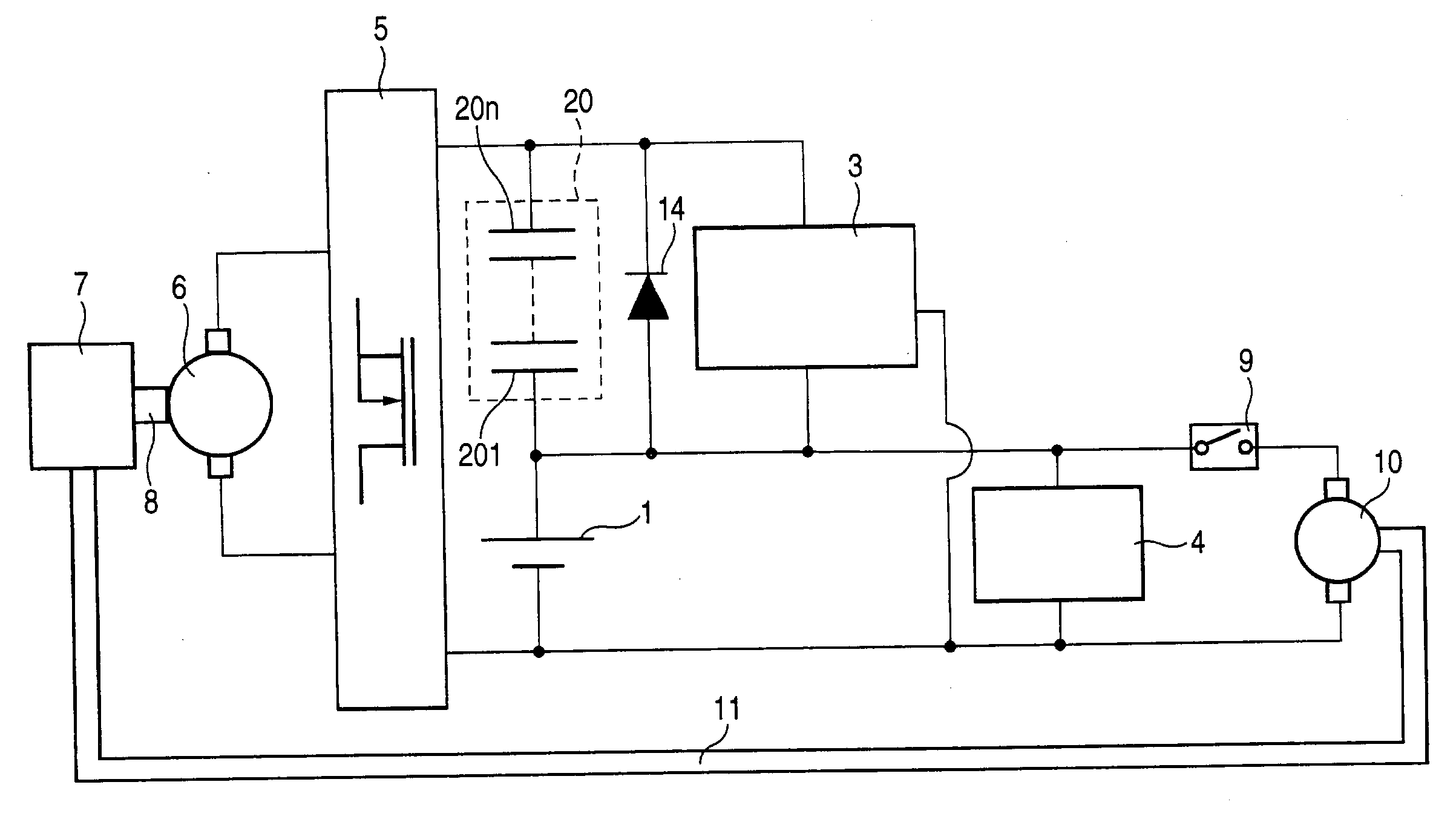
[0047] FIG. 3 is a diagram showing the configuration of an automobile battery power circuit according to Embodiment 3 of the invention. The automobile battery power circuit in FIG. 3 is different from that in FIG. 2 in that the batteries of the battery group 2 are replaced by capacitors. That is, the battery group 2 is formed as a capacitor group 20 constituted by a series body of capacitors 201-20n. As described in Embodiment 2, the capacity of the battery group 2 may be low when the load 4 has a low capacity. Accordingly, not batteries but capacitors can satisfy the specifications sufficiently in some cases. Particularly, of capacitors, electric double layer super capacitors, electrolytic capacitors, or the like, can be used because they can secure high capacitance. Thus, the batteries 21-2n are removed so that the lives of parts can be expected to be longer on a large scale.


PUM


Abstract

A load is connected to a first battery group. The first battery group and a second battery group are connected in series to each other. A bidirectional DC / DC converter for electric power migration between the first battery group and the second battery group is provided.

Description

BACKGROUND OF THE INVENTION[0001] The present invention relates to a battery power circuit for use in a motorcar or the like, which circuit outputs a plurality of voltage levels.[0002] FIG. 15 shows a related-art automobile battery power circuit disclosed in TOYOTA Technical Review Vol. 50 No. 1 Jun. 2000 p.37 or the like. In FIG. 15, the reference numeral 7 represents an engine; 6, an electric motor for transmitting power to the engine through a first power transmitter 8; 5, a power conversion circuit for transmitting electric power to the electric motor 6; and 200, a battery group constituted by a plurality of batteries connected in series, connected to the power conversion circuit 5, and typically having a rated voltage of 36V. The reference numeral 90 represents a load B connected to the battery group 200; 300, a DC / DC converter for stepping the voltage of the battery group down; 100, a battery charged by the DC / DC converter 300, and typically having a rated voltage of 12 V; and...

Claims


Application Information

Patent Timeline
Patent Type & Authority Applications(United States)
IPC IPC(8): H02J7/00H02M3/158
CPCH02J7/0016H02J7/0054H02J2007/0059F02N11/087H02M3/1582Y02T10/7055F02N11/0866H02M3/158H02J7/342H02J2207/20Y02T10/70
Inventor IWATA, AKIHIKOKIKUNAGA, TOSHIYUKI
Owner MITSUBISHI ELECTRIC CORP
Why Eureka
Try Eureka