Constant force golf swing training device, method of swing plane training and internet operation thereof
a training device and constant force technology, applied in golf clubs, weights, clubs, etc., can solve the problems of lack of features of the device taught by fenton, lack of assurance of swing performance, and high cost of many training devices of the art, so as to achieve simple and inexpensive manufacturing, easy to operate, and low cost
- Summary
- Abstract
- Description
- Claims
- Application Information
AI Technical Summary
Benefits of technology
Problems solved by technology
Method used
Image
Examples
first embodiment
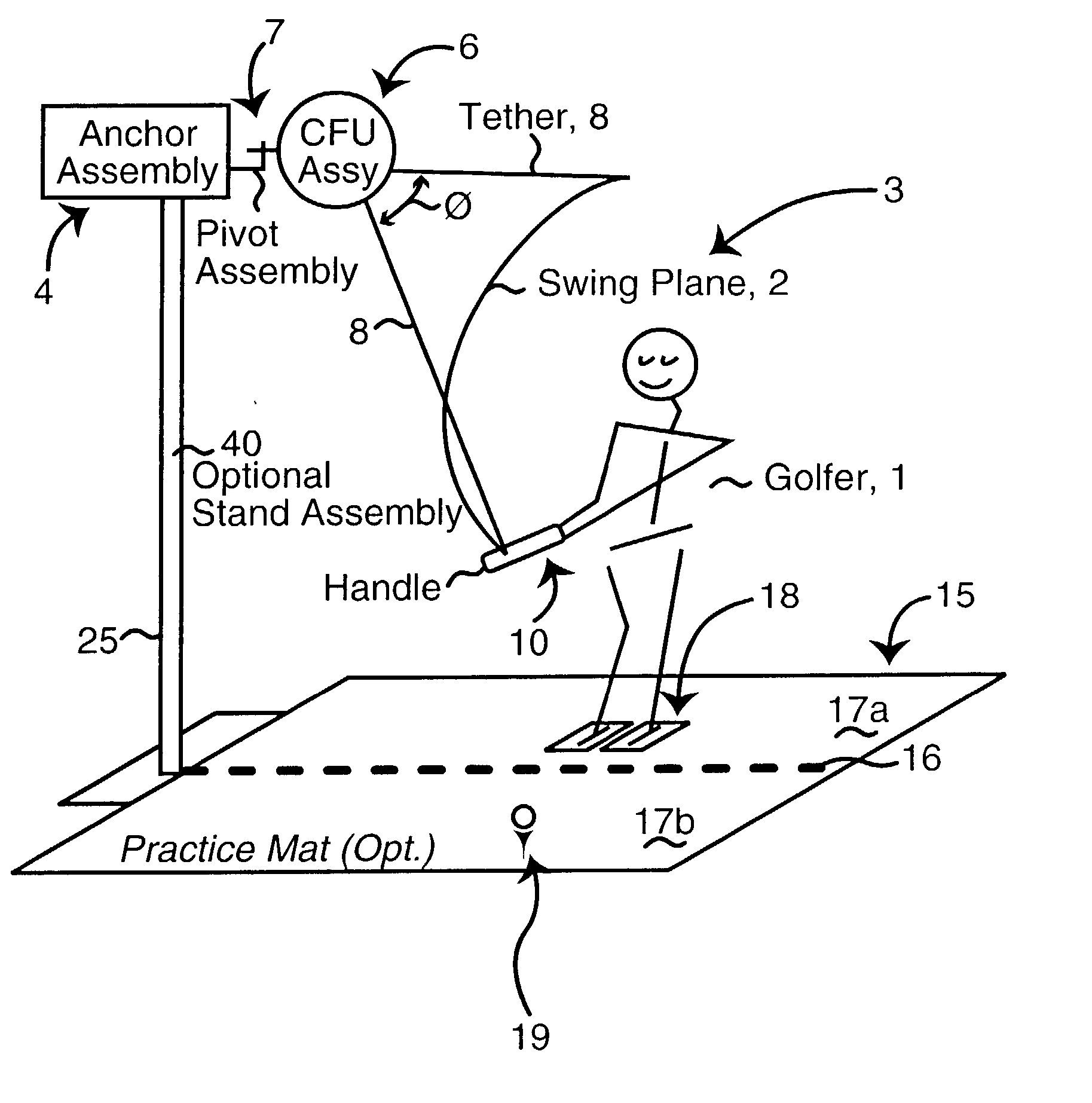
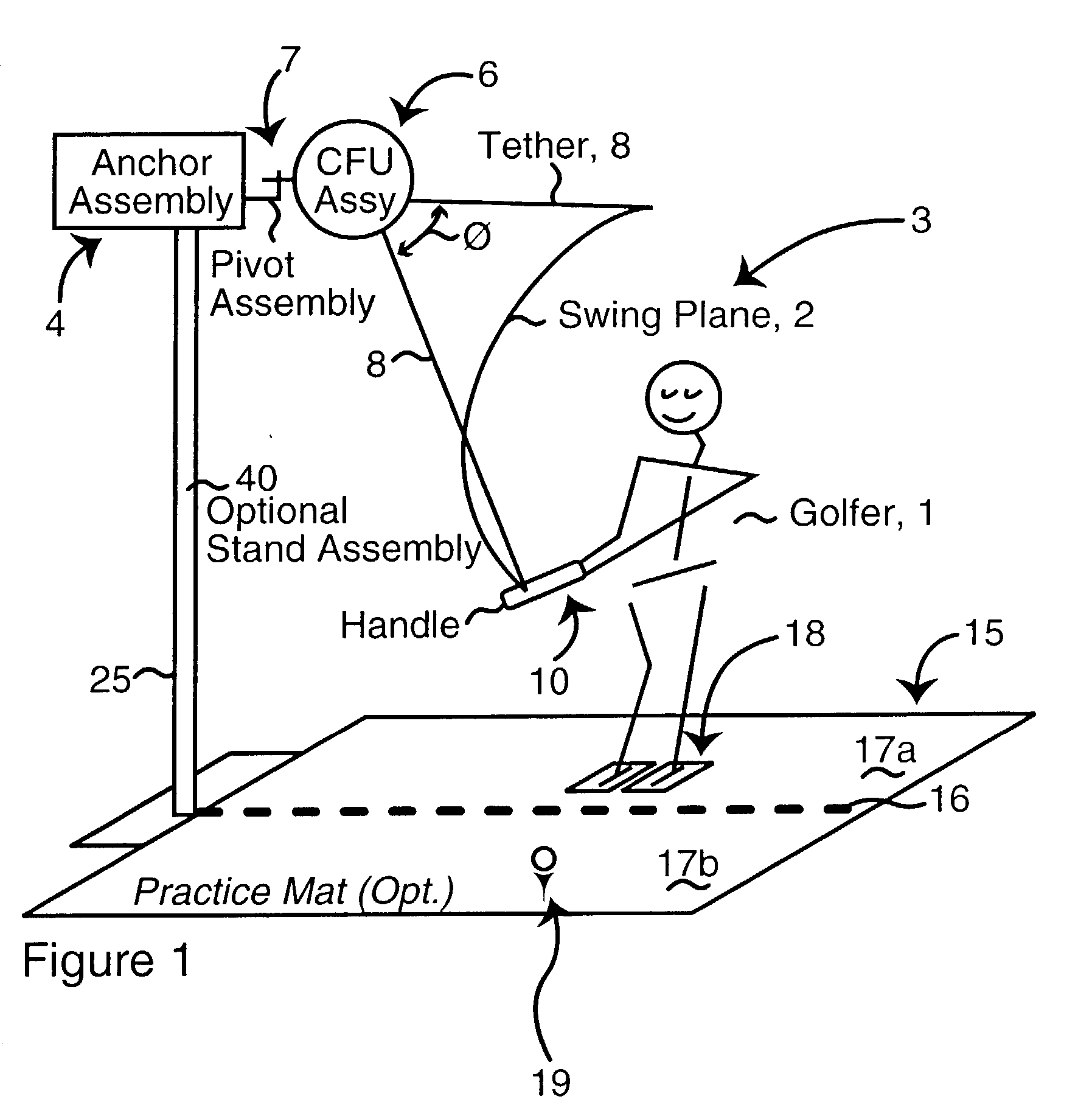
[0052] FIG. 3A is a partly exploded isometric drawing, schematic in nature, of the inventive CFU 6 attached to an over-the-door bracket mounting assembly 4 and showing a single, reverse wound ribbon spring assembly 52. The CFU assembly comprises a housing 50 having upper and lower pins 64 journaled in receiving holes of upper and lower brackets 64 which are secured to the outer plate of the bracket 82. Te pins can be secured with appropriate nuts 62. This pivot assembly permits the CFU to swivel from side to side as the swing plane is followed, so that the force on the handle is the constant force provided by unit 6 without extraneous external forces (friction, vector components) being introduced as in a fixed system.
[0053] Mounted internally of housing 50 is a reverse-wound ribbon spring assembly 52 that provides the constant force and a constant torque rewind function. The tether 8 is wound on the central spool of the output reel 54. Two outer reels receive springs 58 supplied fro...
second embodiment
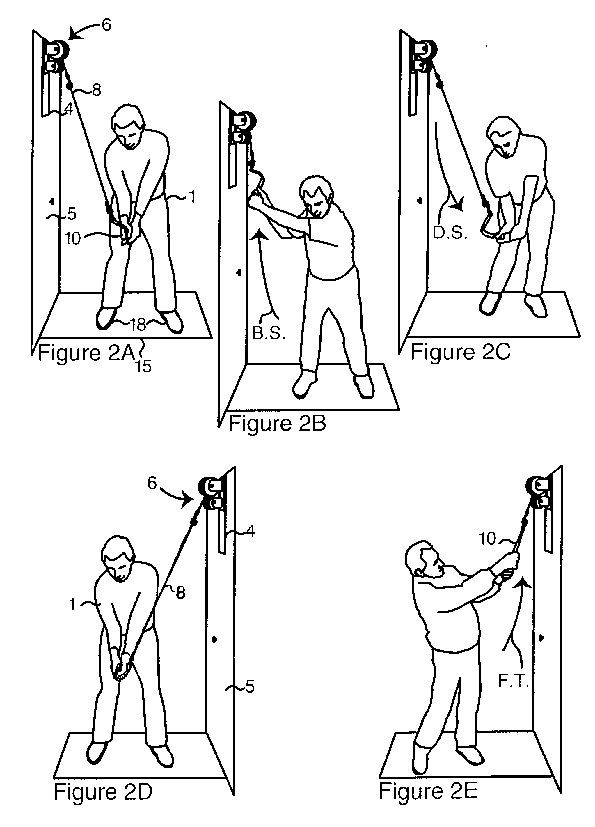
[0056] FIG. 3C is a schematic of a CFU 6 linked to a controller 100 for automatic operation upon payment by coin 104 or credit card 106, and including on or off-site data link 108, via Satellite Dish (SD) or Long or Local phone Line (LL). The external controller 100, or the internal controller 92 can include an annunciator 80 for advising the user of selected messages, such as start, time remaining, number of repetitions and the like. The controller 100 is wired to the CFU controller 92, that is powered via power cord 93. The internal control unit can include a rotatable ring brake 94, see arrow A, which functions to gradually increase resistance on the tether 8 as it is being unreeled. By a full rotation the tether can be completely stopped. The gradual increase in resistance permits the user to complete a swing with out a jarring stop. The swings can be counted by means of reed switch 96 that is triggered each time the swing reaches the low point, FIG. 2C, since the tether 8 moves...
third embodiment
[0063] FIG. 7 shows the CFU 6, in this case a reel that provides constant force through a suitable axial coil spring arrangement 31. The. CFU is mounted on door 5 via an over-the-door bracket 4, and tether 8 is attached to a suitable handle, such as that of FIG. 5C.
[0064] The embodiment of FIG. 9A illustrates a tubular mount system 40 in which the weight system 20 comprises a collar 27 having weights 28 suspended on a rod bracket 29. The collar is free to slide up and down as show by the arrow. The tether 8 is secured to an eyelet on the collar 27, passes up and through the sheave of the pulley 22 of the pulley bracket system 30. The pulley swivels right and left on a pin journaled in the bracket 38, which in turn is supported on the vertically adjustable adjustable bracket 32 by pin 34 engaging a hole 34 in the tube 25 at an appropriate height off the ground. The tube 25 is supported on base 49 to prevent slippage and scoring the floor on which it is resting. A wall mount bracket 4...
PUM
 Abstract
Description
Claims
Application Information
 - R&D
- Intellectual Property
- Life Sciences
- Materials
- Tech Scout
- Unparalleled Data Quality
- Higher Quality Content
- 60% Fewer Hallucinations
Browse by: Latest US Patents, China's latest patents, Technical Efficacy Thesaurus, Application Domain, Technology Topic, Popular Technical Reports.
© 2025 PatSnap. All rights reserved.Legal|Privacy policy|Modern Slavery Act Transparency Statement|Sitemap|About US| Contact US: help@patsnap.com


