Multi-carrier transmission apparatus and multi-carrier transmission method
a transmission apparatus and multi-carrier technology, applied in multi-frequency code systems, multiplex communication, orthogonal multiplexes, etc., can solve the problems of increasing the manufacturing cost of the apparatus, power consumption, heating value, time deterioration, etc., and achieve the effect of suppressing deterioration
- Summary
- Abstract
- Description
- Claims
- Application Information
AI Technical Summary
Benefits of technology
Problems solved by technology
Method used
Image

Examples
embodiment 1
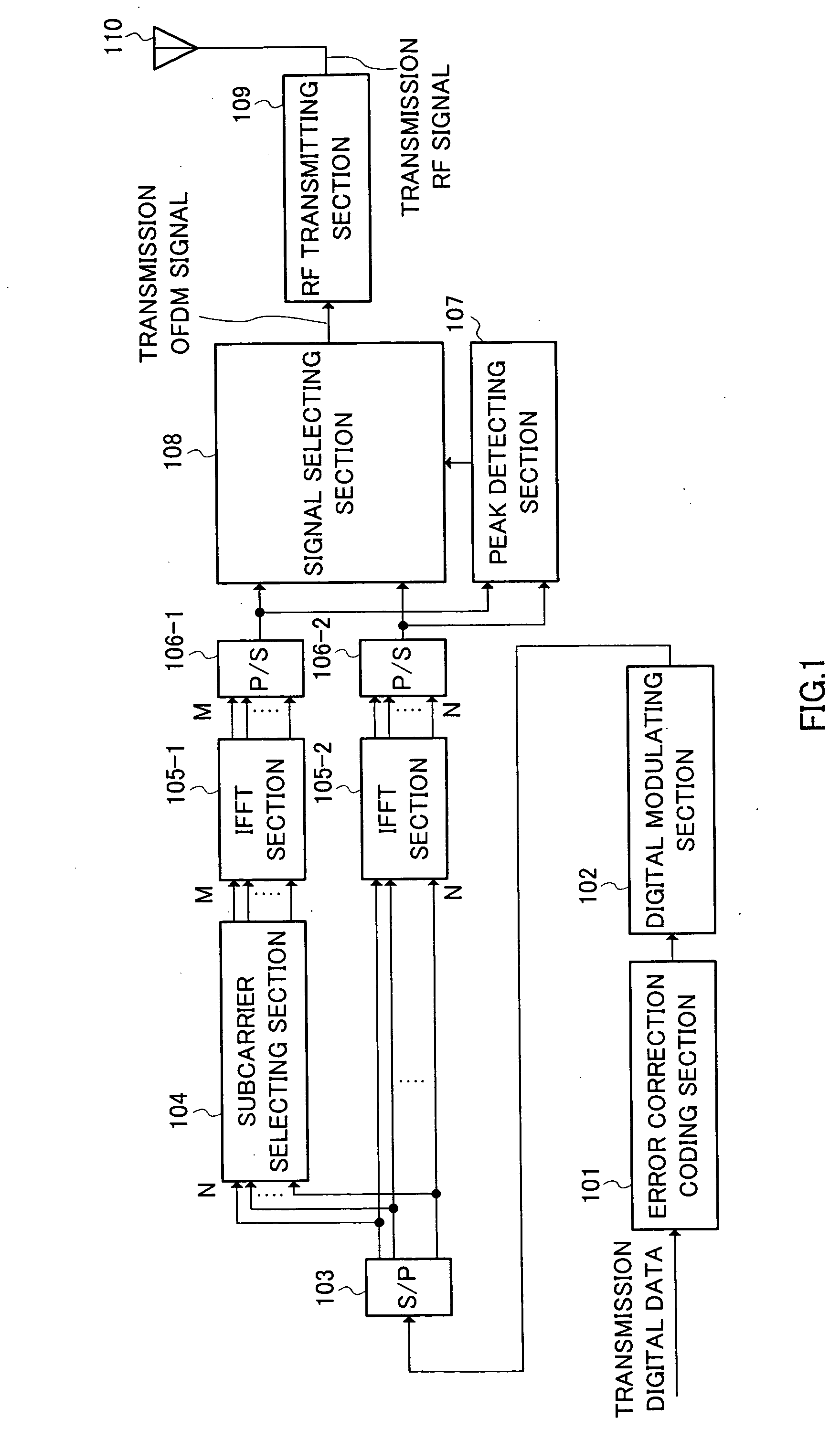
[0022] FIG. 1 is a block diagram illustrating one example of a configuration of a multicarrier transmission apparatus of the present invention. Here, an explanation will be given using an example of a case in which error codes are incorporated into a transmission apparatus using an OFDM communication system.
[0023] An OFDM transmission apparatus illustrated in FIG. 1 includes an error correction coding section 101, a digital modulating section 102, a serial / parallel converting (S / P) section 103, a subcarrier selecting section 104, inverse fast Fourier transforming (IFFT) sections 105-1, 105-2, parallel / serial (P / S) converting sections 106-1, 106-2, a peak detecting section 107, a signal selecting section 108, an RF (Radio Frequency) transmitting section 109, and an antenna 110.
[0024] The error correction coding section 101 error correction codes transmission digital data and thereafter outputs it to the digital modulating section 102. The digital modulating section 102 digitally mod...
embodiment 2
[0041] FIG. 4 is a block diagram illustrating one example of a configuration of a multicarrier transmission apparatus according to Embodiment 2 of the present invention. Additionally, this multicarrier transmission apparatus has the same basic configuration as that of the multicarrier transmission apparatus shown in FIG. 1 and parts in FIG. 4 identical to those in FIG. 1 are assigned the same reference numerals as in FIG. 1 and their detailed explanations are omitted.
[0042] The characteristic of this embodiment is that the subcarrier selecting section 104 shown in FIG. 1 changes subcarriers to be selected according to a repeat request from the receiving apparatus.
[0043] As mentioned above, the number of subcarriers is reduced to M by the subcarrier selecting section 104, with the result that the loss of transmission data is generated. The receiving apparatus sends a repeat request to the transmission apparatus to perform retransmission. There can be considered a case in which when t...
embodiment 3
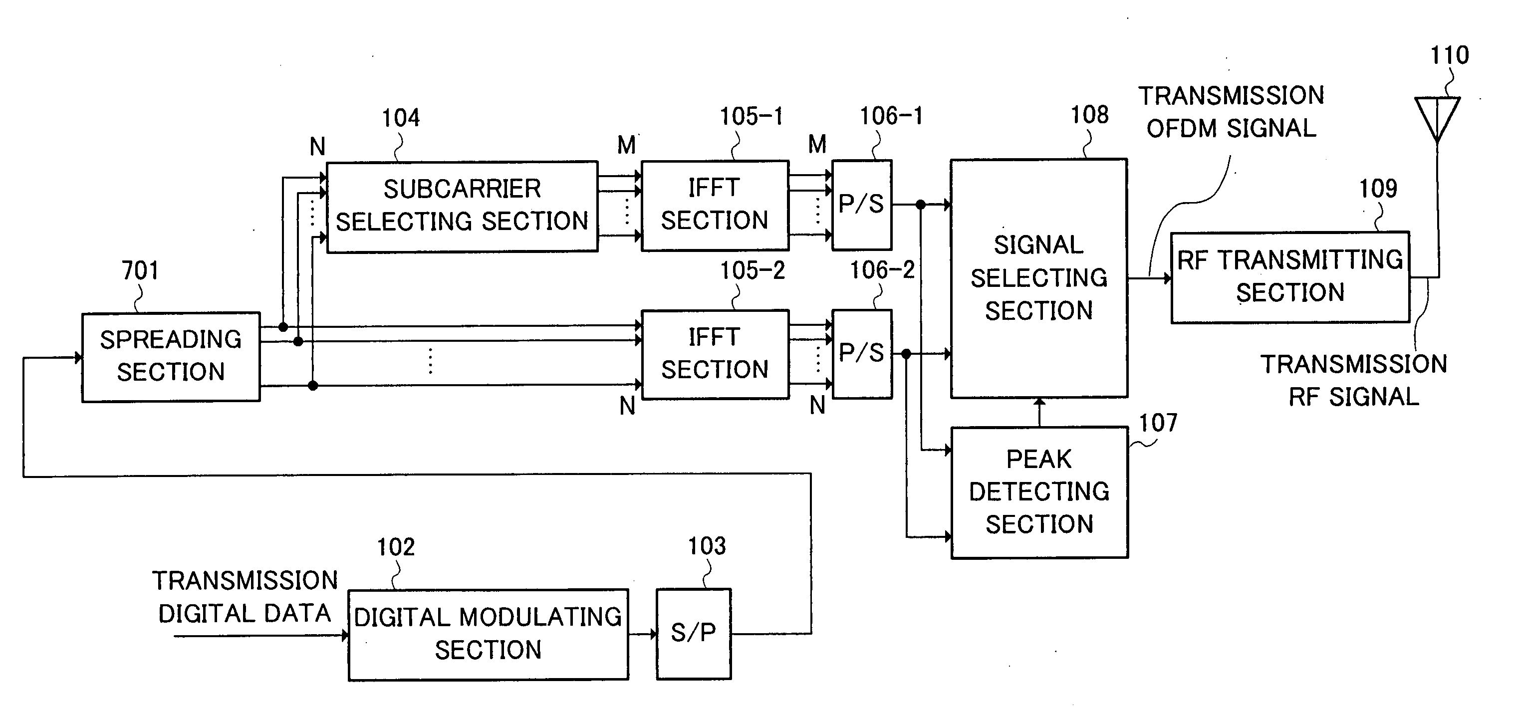
[0047] FIG. 5 is a block diagram illustrating one example of a configuration of a multicarrier transmission apparatus according to Embodiment 3 of the present invention. Here, an explanation will be given using an example of a case in which a frequency domain spread modulation (MC-CDMA) system is employed in a transmission apparatus using an OFDM communication system. Additionally, this multicarrier transmission apparatus has the same basic configuration as that of the multicarrier transmission apparatus shown in FIG. 1 and parts in FIG. 5 identical to those in FIG. 1 are assigned the same reference numerals as in FIG. 1 and their detailed explanations are omitted.
[0048] The characteristic of this embodiment is that a spreading section 501 is provided in place of the error correction coding section 101 illustrated in FIG. 1.
[0049] The spreading section 501 performs frequency domain spread modulation to transmission digital data digitally modulated by the digital modulating section 1...
PUM
 Abstract
Description
Claims
Application Information
 - R&D Engineer
- R&D Manager
- IP Professional
- Industry Leading Data Capabilities
- Powerful AI technology
- Patent DNA Extraction
Browse by: Latest US Patents, China's latest patents, Technical Efficacy Thesaurus, Application Domain, Technology Topic.
© 2024 PatSnap. All rights reserved.Legal|Privacy policy|Modern Slavery Act Transparency Statement|Sitemap